FUEL INJECTION SYSTEM
Download RoverGauge and all 14CUX documents from Dropbox
Note this is far from complete but based on my experiences that you wont find elsewhere - if you think something is wrong or want to add more information on the 14CUX, please drop me an email: Mark@blitzracing.co.uk
Please also have a look at this excellent web page on the 14CUX that covers some areas I have not replicated here: Britishv8.org
OVERVIEW
14CUX was the last in a long line of fuel injection systems made by Lucas who had licensed the designs from Bosch, the inventor of the system. Earlier iterations of this system were called 4CU, 13CU, and 13CUX. The 14CUX is a fuel injection system only, meaning that it only controls the fuel injection on the engine - with the ignition system being kept separate. They don’t have many sensors, and those sensors can be monitored with just a good test meter and as Lucas electrical systems go, these 14CUX systems are actually quite reliable. Sensor wise, these are air flow, fuel temperature, engine temperature, and throttle positions, road speed and on catalytic cars a lambda input. The "hot wire" air flow sensor gives an electrical signal depended on the amount of cooling air that passes over a preheated wire, that's then compared with a reference hot wire that has no cooling air flow. The various sensor inputs are then fed into the ECU, and converted into a digital signal that addresses a pre-determined fuel map held in a 27128 or 27256 type Eprom to give an injector pulse signal appropriate for the fuel requirements of the engine at that point. The ECU controls the fuel allowed to each cylinder by changing the time the injectors are open for (batch firing them), combined with a variable fuel pressure regulator on the end of the fuel rail. This regulator alters the fuel pressure dependent on what the inlet vacuum is at any given moment and will vary from 24- 37.5 psi. The Fuel Regulator is set to 2.5 bar or 37.5 psi if the inlet vacuum pipe is open to the atmosphere. This simply maintains the fuel pressure at at a set value above the pressure in the plenum chamber, so exact fuel metering can be maintained. To maintain a steady tick over, there is a stepper motor that controls an extra air path past the throttle body.
ECU MODES OF OPERATION
Emission Compliant (Catalysts) Mode
All production cars post August 1992 (UK) have to run in this way with a catalyst fitted in the exhaust system. Here the air fuel ratio is clamped at 14.7:1 under normal running conditions (up to 3400 rpm or 3/4 throttle) as this is the point chosen for the Rover V8 engine, to be near to the ideal 14.7:1 air fuel ratio that is considered the best point for a complete fuel burn and minimum exhaust pollutants (referred to as lambda 1). Due to the old design of the engine it wont run nicely that lean, so this compromise was reached. Due to the way the emission regulations where written in the 1990's the catalysts fuel mapping and lambda feedback is disregarded above 3400 rpm or 3/4 throttle to allow the engine to give best performance, at a point when emissions are not measured.
Non Catalysts Mode
It can also be run without catalysts and no pollution restraints allowing for a much wider range of air fuel ratios between 12.5:1 and 15.5:1 depending on the engines requirements. On the whole standard engines run better in non catalyst mode as the base mapping is set to suit the engine design, and this mapping was used on UK vehicles pre 1992 and the catalyst laws.
The two modes of use are referred to open loop (no lambda feedback) for non catalyst use, and closed loop (with lambda feedback) for catalyst use.
There are both pros and cons for running in ether modes:
Non Catalyst Open Loop
Non catalyst mode allows the engines ideal air/fuel ratios to be maintained to suit the best running of the engine in all conditions. This allows the engine to run leaner under light cruising leading to better economy, and slightly richer at a low RPM which suits the Rover V8 engine. There is also a limited mixture adjustment that can be altered from a setting on the side of the A.F.M under and the low speed fuelling can be tweaked for a smooth idle and smooth running up to around 2500 rpm. This mode is of most use where a high performance cam is used, as the A.F.M measurement does not cope well with the poor/pulsed air flow produces at low RPM by a performance cam, so fuelling can be inaccurate, and this effect can be reduced by altering the mixture to an extent. A big downside to running a non catalyst set up, is the ECU relies totally on the fixed fuel map parameters in the ECU, so any engine modifications can make this data incorrect, so the ECU may need to be re-chipped to suit. It also wont pass the emissions tests at MOT time, as the wide variances in air fuel ratio, and resulting shifts in exhaust pollutants are over too wide a range for the catalyst to correct.
Catalysts Mode, Closed Loop
In catalysts mode the ECU can compensate for an incorrect mixture outside the desired 14.7:1 air fuel ratio, by altering the mixture by up to + /- 20% on the fly depending on the readings from the Lambda sensors. The ECU will automatically trim the mixture once it gets a signal from the Lambda probes showing an over rich or over lean condition and will simply apply a series of steps (up to 1024) to correct the mixture until there is a shift in lambda output showing the mixture has now crossed the 14.35 A/F ratio point. The cycle is then reversed to swing the mixture the other way, and the process repeated, and can be observed by a rough 1 volt square wave signal from the probes as the mixture cycles. The majority of fuel trimming takes place each time the car idles, and all the sensor inputs are stable, and once this is set only small adjustments should need to be made from this point onwards. It will then constantly correct the mixture under various load conditions with small corrections, but if large corrections are made it can be picked up as poor throttle or snatchy response. If large corrections are needed there is either a problem with the basic fuel map being incorrect, such as when the engine has been significantly modified and is still running a stock fuel map, or there is a new hardware fault. This lambda feed back will allow the system to compensate for engine modifications to a reasonable extent, whilst maintaining low emissions but the down side of this can be poor low speed performance where the engine develops a shunting type behaviour with a performance cam as the ECU battles to keep the emissions low. This is part due to the poor pulsed breathing of performance cams at low R.P.M when an A.F.M is used to measure the airflow, combined with the lambda cycle. You can get a similar condition at higher speeds if the engine has been significantly modified as the ECU runs out of correction range, so the base fuel map will need changing to reduce the amount of correction needed. Another downside of the catalysts mode it clamps the mixture slightly richer than it needs be under light load to keep the un burnt hydro carbon pollutants to a minimum, so the economy suffers slightly. The ECU only tries to maintain the emissions up to 3400 rpm, or about 3/4 throttle, and beyond these points it simply fuels the engine dependent on the fuel map data, so the performance is the same as a non catalysts open loop setup.
Many people are now replacing the 14CUX with a more modern ECU, that can accurately supply the engine with the required mixture, by using wide band lambda sensors and hopefully still comply with the emissions requirements, although this may prove difficult in some cases where these ECUs are programmed for maximum power over emissions. In a way this is going back to the non catalyst fuelling mode, but the 14CUX does not have the advantages of wide band Lambda sensors to trim the mixture if its wrong. It also cant control the ignition spark, unlike some of the more comprehensive after market ECU's as one of the poorest parts of the Rover V8 set up is the ignition timing and general spark control.
This chart shows the generic catalysts closed loop point, as on the RV8 the closed loop point is set fractionally richer to allow for the old design of the cylinder heads.
Switching ECU Modes
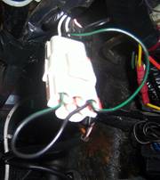
This is easily done by changing the “tune” resistor that is found poking out of the wiring loom near the ECU. Changing the value of this tune resistor will change the fuel map used, with a total of 5 maps being available. The original Lucas resistors have a coloured sleeve on the resistor wires, and frequently the map used will be referred to by the colour of this sleeve, as say the green tune which in this case is a non catalysts UK map. Some later wiring looms don't have a tune resistor fitted at all, as by default the ECU will run in full catalysts mode without it.
White 3900 Ohms USA and European vehicles with catalytic converters
Green 470 Ohms UK and European vehicles without catalytic converters
Yellow 910 Ohms Saudi vehicles (without catalytic converters)
Red 180 Ohms Australia and the rest of the world
It is perfectly possible to easily switch maps by using a switch to change resistor values or using a variable resistor, but it needs to be done with the ignition off, and it tends to generate a fault code on the ECU showing tune resistor out of range. This will throw the ECU into limp home mode, and will require the ECU to be unplugged from the wiring loom briefly to clear the fault code. It’s not advisable to run a non catalyst fuel map if the physical catalysts are fitted in the exhaust, as the less controlled fuelling may lead to the catalysts overheating and melting that can lead to dangerously high temperatures, followed by exhaust blockage as the catalyst breaks up. It is perfectly acceptable to run either catalyst or non catalyst mode on a car without catalysts however.
WARNING: If you have a modified chip (ie non Range Rover standard), and you want to switch maps the alternate map may not be suitable for your engine specification, as you may switch from a modified fuel map to a non modified fuel map that is totally unsuitable. If in doubt check with the chip supplier!
ECU Initial Start-up Sequence
The sequence to restart the engine actually starts as you turn off the ignition switch. As the ignition voltage is removed from the ECU, the unit sends out a signal to the stepper motor attached to the plenum chamber to wind it fully backwards and allow maximum air into the plenum chamber. This can be heard as a buzz from the stepper motor as the engine dies. As the ignition voltage has now gone, the engine simply stops with the stepper motor in maximum air position.
On turning the ignition back on, a short pulse (about 1- 3 seconds) is sent to the fuel pump to pressurise the fuel rail. Once the starter motor starts to turn the engine, a 12v pulse is fed back to the ECU from the negative side of the coil as it the ignition amplifier switches. The ECU then turns on the fuel pump and energises the fuel relay that provides a fixed 12 volt supply to all the injectors. The transistors in the ECU starts to ground the injectors with a longer pulse than the normal idle pulse for about 3 seconds. This provides enough fuel to start the engine, combined with the stepper motor still being in its wide open position. Once the engine has fired, the air flow meter then takes over feeding the air flow volume back signal to the ECU and the injector pulse width is reduced to match the fuelling requirements for the engine at tick over. The stepper motor is also wound in to stabilise the idle at around 800 RPM. This system accounts for the short burst of higher RPM at tick over as the stepper goes from wide open to part closed during the start process.
One side effect of this system is if air leak develops any where in the inlet system, the engine will start and run for 3-4 seconds and then die. The initial over rich mixture will allow the engine to run, but once the air flow volume comes into play, (Now reduced because of the air leak) the injector pulse width is reduced to the point where the is insufficient fuel to keep the engine running, so it dies. The whole pipe work and breather system around the plenum chamber is pretty finely balanced and can be easily go out of tolerance should an air leak develop.
Fuel Control Components in Detail
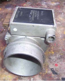
Air Flow Meter (A.F.M.)
The air flow meter with a hot wire sensor, sits inline with the air intake and monitors the actual mass of air being drawn by the engine by the cooling effect on the heated wire. It also has built-in temperature compensation, so cold denser air produces a higher voltage output than warm air. This is the main input the ECU uses to control the amount of fuel going in, with a 0 -5 volt output dependent on air flow, with all the other sensors just being used to “trim” the basic fuelling. The A.F.M is very sensitive to changes in air flow at low volumes, but becomes progressively less sensitive as the airflow increases and on some tuned 4.5 to 5 ltr engines the 5 volt limit is reached before peak airflow, so the output “flat lines”, and no further information can be derived from this sensor. There is also a “C.O. Trim” setting on the side of the A.F.M that is used to adjust the idle mixture (up to around 2500 rpm) on non catalyst fuel maps, as there is no Lambda feedback to allow automatic trimming of the mixture.
Setting The Air flow Sensor Applicable to NON catalyst cars only. Using a voltmeter between red and black wire and blue and red wire check the voltage with the ignition on, but the engine not running. Recessed Hex head screw allows you to set the carbon monoxide base line with these voltages. NOTE these are base settings ONLY. Turn the adjustment screw clockwise to richen the mixture, and anticlockwise to lean the mixture. The screw has multiple turns, that will go from 0 volts to over 3.5 volts.
This unit has 4 connections:
| Red/Black | Ground |
| Blue/Green | Air flow signal- should be .2-.7 volts (no air flow). Tick over on the 3.9 is about 1.7 volts |
| Brown/Orange | +12v |
| Blue/Red | CO trim value. This is factory set 1.8 volts for catalyst engines, although I believe this setting is ignored with Lambda correction. Non cat cars are in the range of 1-1.5 volts, although accurate setting will require the use if an exhaust gas analyzer. |
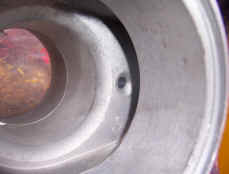
To test the air flow sensors output, connect the meter between the the ground (red black wire), and air flow sensor output (blue green wire). By removing the air filter and looking into the mouth of the air flow meter, a small hole will be seen in a cutout that runs around the edge of the air intake. By blowing gently into this hole the voltage should rise sharply on the airflow output. Not a scientific calibration, but a basic confidence check. (more accurate testing below).
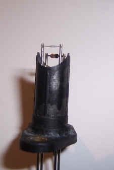
This is the hot wire sensor (enlarged). The grey sensor in the foreground is the actual hot wire sensor, with a temperature sensing thermistor behind it. The hot wire can get coated in road dirt, that changes its cooling characteristics and causes the output from the AFM to be incorrect. It is difficult to clean without removal, although a blast of "easy start" or the like might be enough. Removal requires a complete strip down of the AFM to remove the electronics board. The hot wire connections are also spot welded to the PCB, and very difficult to re-solder reliably.
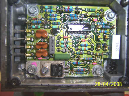
This is the internal electronics module. You have to cut around the plastic cover to remove the sealant, and then remove a metal shielded plate to get this far. Electronically is pretty simple, with just a single op-amp IC to measure the output change from the hot wire itself. There are several trim resistors used to calibrate the unit, with R24 having the greatest effect. The variable resistor seen on the right simply connects between the "pot" connector and ground, and is used to set the idle mixture on the ECU. This has no effect on the operation of the AFM electronics.
Fitting Larger AFM's
It's perfectly possible to fit a larger AFM to highly tuned engines (£250 bhp +) to remove some of the restrictions caused by the stock Lucas unit. These are normally the Bosch AFM used on the later Lucas G.E.M.'s Engine management systems used on the Range Rovers, or the larger Lucas 20AM A.F.M. There will normally need some minor wiring loom modifications plus a new fuel chip.
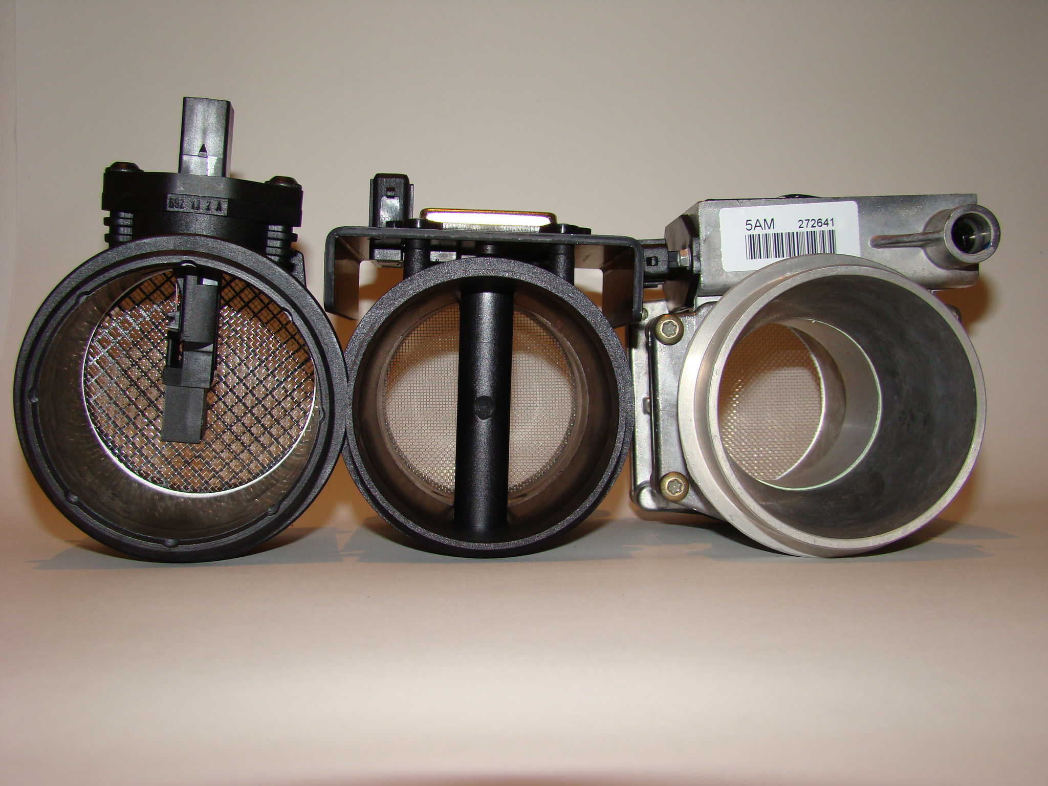
Bosch MHK100800, Lucas 20AM and standard 5AM showing the difference in cross sectional area. The wire gauze is needed to reduce the turbulence around the airflow sensor.
Photo thanks to Mark Adams
The voltage output of the Bosch and Lucas 20AM are still 0 to 5 volts, but scaled differently against the airflow values. The Lucas/Sagen 20 AM is an easier unit to work with as its voltage is simply about 15% lower than the 5AM across the range. The Bosch unit starts with an initial higher voltage, that then reduces as the airflow increases. Ive tried to rescale these outputs to match the 5AM, but even once this is working you don't gain anything much as the fuel map is designed for the peak airflow with a Lucas 5AM, so any extra air the larger AFM lets in is not recognised in the map, so no additional fuel is added. Re-mapping is the best option to make use of the extra airflow.
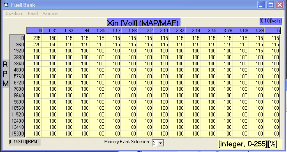
This is the rescaling values for the 20AM- The top line shows the percentage of additional voltage required with 100% being no change - ie a reading of 150 means the voltage has to be increase by 50% at this input voltage.
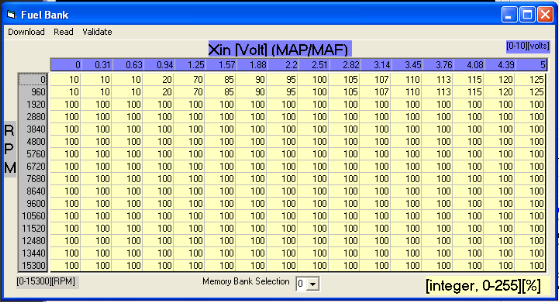
This is for the Bosch unit, with a much wider voltage range.
Lucas 5AM Airflow meter testing. With thanks to Mark Adams of Tornado Systems
Most airflow meter faults will cause the engine to run excessively rich. However if the airflow meter remains connected whilst defective then the vehicle will probably not run. In most cases the output from a defective airflow meter will be in the range 2.0-2.5 Volts, which is a viable value. This represents a moderate load and will cause heavy over-fuelling without setting a fault code.
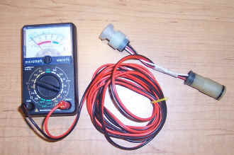
Testing is performed in the following manner. Peel back the rubber boot on the airflow meter connector and leave it plugged in to the airflow meter. Set up the digital multimeter to read voltage. Insert the negative probe into the Red/Black wire (sensor ground), and the positive into the Blue/Green wire (Airflow signal).
Turn on the ignition, but do not start the engine. The meter should immediately indicate a reading of approximately 0.3-0.34 Volts after the initial "warm up" spike. Most defective airflow meters will overshoot to 0.8 Volts or higher, and take at least 2 seconds to come down to the correct voltage.
This is the correct waveform for the AFM when it's first powered on, followed by the engine being started. This trace of 1.62 volts is a 3.9 at 800 rpm.
Now start the engine, and the reading should rise to 1.6 Volts (3.5 Litre engine) to 1.75 Volts (5.0 Litre engine).
The next test is full load, and as with the fuel pressure test it will require use of a rolling road or a steep hill in the same manner. Under full load the voltage should rise to 4.45 Volts (3.5 Litre engine) to 4.95 Volts (5.0 Litre engine).
On non catalyst systems, the idle CO mixture adjuster is provided on the airflow meter. It is located in a boss on the top of the airflow meter, pointing towards the engine. Leaving the multimeter negative probe in the Red/Black wire, move the positive probe to the Blue/Red wire.
Now turn on the ignition but do not start the engine. Observe the voltage. The normal adjustment range is between 0.0 and 3.6 Volts, with the higher Voltages producing higher idle CO values. There are approximately 20 turns of the adjuster screw to cover the entire range.
Annoyingly, the adjustment may be clockwise or anti-clockwise to increase the value, and this varies from meter to meter! For this reason it is always preferable to have the multimeter connected in this manner when adjusting idle CO, so that you see can something is actually happening.
Typical Voltages that would be found at this point are between 0.9 to 1.4 Volts for non-catalyst cars. This Voltage is always factory pre-set to 1.8 Volts for catalyst vehicles. A value near to 3.5 Volts will generally produce an idle CO value of 9-10%. These Voltages may be used as safe initial values particularly if no CO measuring equipment is available.
Fuel Temperature and Engine Temperature Thermistors
Found in the fuel rail and inlet manifold. These two sensors have the same temperature to resistance values, but are physically slightly different. The response not linear, with colder values having a much larger resistance change per degree than the hot values.
10C(14°F)
0C(32°F)
20C(68°F)
40C(104°F)
60C(140°F)
80C(176°F)
100C(212°F)
9100-9300 Ohms
5700-5900 Ohms
2400-2600 Ohms
1100-1300 Ohms
500-700 Ohms
300-400 Ohms
150-200 Ohms
Road Speed Sensor
This provides a 12 volt switched signal dependent on the how fast the car is moving. Its trigger point is 3mph, then the ECU alters how the stepper motor controls the idle (see below) and it also provides information to the ECU to limit the top speed on some 4x4 vehicles due to the limits on off road tyres. This unit is replaced on some TVR’s by an electronic unit called a speedometer calibration unit, (found under the dashboard ) that simply gives a fixed speed signal above 3mph, but no top speed signal. This top speed limit can also be removed by reprogramming the engine fuel map within the ECU.
Throttle position sensor
(variable resistor or throttle pot’.) found on the side of the plenum chamber alongside the throttle body.
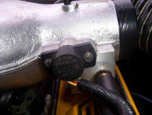
On early 14CU systems this had a manual adjustment to set the lower limit voltage, but with the advent of the 14CUX, it became self calibration, so the elongated holes where removed. This was OK up to a point, but its still possible to exceed the units ability to self calibrate, so the holes can be elongated to reach the required values.
The following voltages are within the units self calibration range.
Voltage measured between the red wire (+ve ) and green (-ve)
Throttle closed .085 - .545 volts
Throttle wide open 4.2- 4.9 volts
The voltage swing between throttle open and throttle close should be smooth and linear.
If these voltages cannot be obtained then you may have a raised idle, or lack of full power enrichment under full load. Although this does not control the fuelling directly unlike some other systems, but is used to detect specific engines conditions by its position or the rate at which its being moved at and these are:
Throttle closed position from engine start. This allows the stepper motor to control the idle at around 800 rpm when combined with zero road speed signal.
Throttle part open to full throttle with road speed sensor input. This causes the ECU to lift the idle setting to higher than normal via the stepper motor, (about 1200 rpm) so the engine breaking is reduced when changing down. Rapid throttle opening causes a rapid resistance change that the ECU picks up as a rapid acceleration requirement, so the ECU then adds extra fuel to richen the mixture. This is done buy removing the tight mixture control used in the closed loop catalysts setting, and allowing the engine to run open loop and a much richer fuel air ratio, so maximum power can be produced. This occurs at above 3400 rpm or 3/4 throttle, which ever condition occurs first. The mixture is also maintained in a richer condition when the throttle is held wide open for power and to prevent engine damage under heavy loads and high temperature.
Part closing the throttle causes the ECU to try and weaken the mixture for light cruising, but when used in closed loop the ECU overrides this and pulls the mixture back to 14.35: to minimise the pollutants and unfortunately this reduces the fuel economy for the sake of reduced pollution. If the ECU is being used with a non catalysts fuel map, it will let the engine run as lean as 15.4:1 A/F ratio in this condition.
Fully closing the throttle combined with a speed sensor input causes the ECU to shut the fuel off for a period, but not so much it will let the idle drop from its elevated “car moving” condition. Once the speed signal stops the idle is then reduced to normal idle.
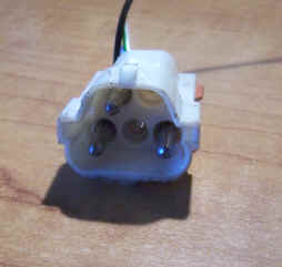
Lambda Probes
Lambda probes (post August 1992 engines) generate a voltage dependent on the amount of remaining oxygen in the exhaust after the burn has taken place. The voltage should be within the range of .0- 1. volts, with 0 being lean and 1 being rich cycling around an optimum point of 14.7:1 air fuel ratio but the voltage may peak as high as 1.2 volts as the ECU makes bigger mixture compensations during the long term trim period, or when the ECU is in open loop. Its worth noting that the probes have a reverse voltage response curve to generic probes and are only fitted to the Rover engine and a few Nissans. They also have a heater coil fitted that is powered from the fuel pump relay, so give a rapid warm up time. The physical probe element is resistive, but a voltage supply is provided from the heater supply to the probe, so it effectively produces a variable voltage output, without a supply from the ECU, so if the heater supply is missing the probe will give a 0 volt output even when its hot. Once the ECU is powered on, it will not modify the fuelling until it receives its first changing signal from the probe, but from this point it expects a regular signal and if the signal fails or goes out of range it will generate fault codes showing fuel supply/injector problems or lambda faults.
Wire Colours
| LOOM | FUNCTION | PROBE |
| White/Orange | Heater | Red |
| Screened Blue | Probe Signal | Black |
| Black | Ground | White |
Observing Lambda Signals
A huge amount of information can be derived from the switch rate and waveform of the lambda probes whilst the car is in closed loop. This can be done with a good analogue test meter although a digital one will do as a push, although due to the way digital meter reads the voltage its difficult to read the mark space ratio of the signal. Alternately an LED bar graph type meter used for measuring audio signals (VU meter) can be adapted to make an easy to view display. With a long enough lead the signals can be observed by a passenger from the cabin, whilst road tests are performed.
These Waveform readings are taken using a low cost Data Logger

This is the correct lambda pulse at idle on a 3.9 engine. The slightly wider pulses show extra fuel trim being added to lean off the mixture, whilst narrow pulses are slightly too lean, so this cycle constantly adjusts. This can lead to a slightly irregular idle. Bigger engines tend to have a lower lambda cycle rate, sometimes nearing 1 second per change.
This shows a typically over-rich condition (by boosting the fuel pressure). The wide pulse voltage is slowly seen dropping as the ECU applies more and more fuel trim, until it hits the point the lambda probe changes state. As can been seen by the ragged waveform subsequently the ECU is not managing to accurately control the mixture as the fuel trim off set has now become too wide.
This shows an over-lean condition by introducing an air leak to the plenum. The Lambda output has remained near 0 volts until enough trim offset is applied to correct the mixture, and at this point the mixture is being clamped correctly again.
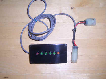
A bespoke LED reader for Lambda outputs. The first 4 LED's read the 0-1 volt range, and the orange the 1 to 1.2 volt rage for open loop. Unfortunately this upper region is not 100 % consistent between probes, so can only be used as a rough guide.
In an ideal world the basic fuel map will be perfect for the engines/emission requirements. This will mean the absolute minimum of fuel trim needs to be added or removed to get the mixture perfect, so the ECU has to add or remove very little fuel to get the probe to switch state. This leads to a rapid and even switch wave form as seen in the first waveform diagram above. The switch rate will increase even further as the engine RPM increases and the airflow increases if alls well. If however the mapping is wrong, or something else is throwing the air fuel ratio out (like air leaks, bad sensor inputs, wrong fuel pressure) the switch rate will slow significantly as the ECU adds more and more trim. In the worse case the switch signal may stop all together for periods showing the ECU has run out of correction range.
The open loop area of the fuelling is easier to monitor, above 3400 rpm or 3/4 throttle and should give at least a static one volt signal, although new probes may give up to 1.2 volts. If this cannot be maintained then the mixture is too lean, and the engine may become damaged under load.
Idle Control System - Stepper Motor
This is a fairly crude affair, utilising a air bypass screw (called the base idle setting) and a simple stepper motor controlled air valve to keep the idle steady as the engine loads vary. The stepper motor has 180 different step positions, and each time the ignition is turned off, the stepper motor pulls the air valve wide open, by being pulsed 200 times. As only 180 steps are available, it will always reach a "home position", and from this point the ECU keeps track of its position by counting pulses from the home position.
Idle Stabilising System and its problems
The stepper motor is always the first culprit for unstable tick-over, but due to a very crude "pulse and wait" system used by the ECU to stabilise the tick over, other factors like wrong CO settings, air leaks and wrong timing can cause the the engine revs to rise and fall as if the stepper motor was sticking. If you have cleaned the stepper motor shaft (as below) then look else where before replacing the stepper motor.
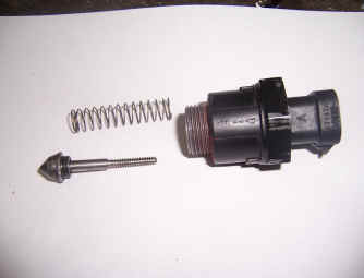
Air control valve. This comprises of a stepper motor, with a worm drive that moves a conical valve to control the amount of air by passing the throttle butterfly, and hence the tick over. Very prone to sticking due to carbon and oil build up from the plenum chamber (made worse by using a sports camshaft), leading to erratic tick over.
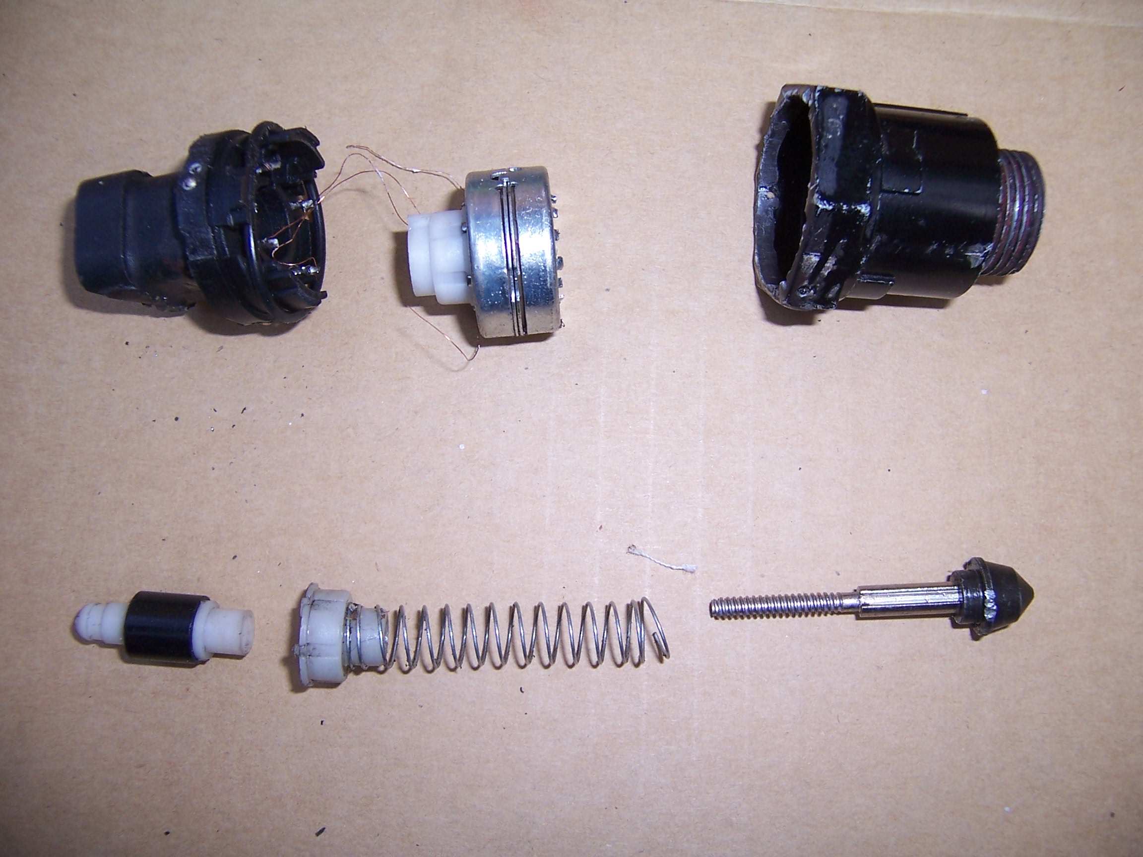
Component parts, comprising of motor, tension spring, control valve, rotor and screw cap. There is also a metal bearing in the housing that can become dirty and corroded. Its not possible to strip a unit this far unless its scrap!
Cleaning the Stepper Motor
At its simplest, the motor can be unscrewed from the plenum housing, and all the carbon and oil deposits removed from the head of the metering cone, and some use of carb' cleaner on the keyway may be enough to get the unit working. It’s also worth cleaning out the metering hole inside the plenum. If it still sticks then more drastic measures may be needed. I have now perfected a way of getting these bits to clean, without damage:
- Get the car warm
- Remove the stepper from the plenum and reconnect it
- Block the hole the stepper has come from with something air tight, or even the palm of a hand
- Hold the stepper so you can catch the central cone and spring when it comes out
- Get someone to start the car. Without the stepper in place it will rev at around 2k- 2.5k (This is noisy!!), but the ECU will try to slow it down by powering the stepper motor and pushing cone outwards. It will do this in a series of pulses, a few seconds apart, until the cone and spring drop out. (assuming they are not completely stuck). It may take a bit of manual help to get the cone to fully release. Now stop the engine and let it cool.
- Clean all the muck off the shaft and cone, and lightly lubricate the screw thread inside the motor
- To reassemble, wind the shaft back into the motor so far, but align the slot in the shaft with the plastic keyway as best you can by rotating the shaft in its screw thread.
- With the engine cool, then reconnect the stepper motor. Power cycle the ignition on and off, (don't start) and the ECU will try to pull the shaft back in each time the ignition is turned OFF. This is the slightly tricky bit, as if the keyway and shaft are not quite aligned it wont pull home, so you may need a few attempts.
In a few cases cleaning does not resolve idle issues, and this can be due to corrosion in the metal bearing in the rear of the stepper housing becoming mucked up or corroded, and this requires a new unit.
The component parts. Clean the cone, shaft and keyway.
One weakness of this system, is if the stepper motor sticks, the ECU loses its correct position, as there is no feedback to say where it is which leads to an unstable idle. Another weakness is how it crudely controls the tick over. If the engine is running above the required RPM at tick over, a burst of pulses is sent to the stepper motor to reduce the air supply. The ECU then waits a few seconds for the mechanics of the engine to respond. This time "constant" depends on the engine dropping its RPM in a fairly controlled manner. Further tweaks then take place if the RPM is still outside tolerance. A problem occurs if the engine RPM drops faster than predicted due to fuelling errors, or ignition problems, so the engine RPM drops too far. After the wait time the ECU detects the RPM is now too low, and winds the stepper motor back again and waits again, at which point the RPM goes too high. The process then repeats itself, so the idle remains very unstable.
Cheap eBay Stepper Motors
The OEM part typically costs between £70 and £90, but there are cheap units for around £20 available on eBay. These are Chinese copies, and on the whole have proven not to work well. The biggest issue is air leaks around the motor, or the shaft length being about 4mm too long. The shafts can be removed (as above or using RoverGauge) on these and then cut down to match the original shafts and they will then work. The shafts are not interchangeable between the OEM and copies.
Other Factors Affecting Tick Over
1) Correct Air Fuel Ratio
The ECU will get its total airflow reading from air through the A.F.M, and supply a relevant amount of fuel for this airflow. Problems occur if there are any air leaks anywhere in the plenum feed pipe, plenum chamber seal, stepper motor housing, stepper motor itself, vacuum pipe to fuel regulator, vacuum pipe to distributor, or a split diaphragm in the distributor advance mechanism. Everything is very sensitive, as the actual airflow through the AFM is very low at this point, and any air leaks will significantly reduce this reading so the ECU reduces the amount of fuel to the injectors. The engine then leans out and the RPM drop is rapid. This is combined with a high vacuum in the plenum chamber as the throttle plate is shut, so any small leaks in this area have a much greater effect due to the greater pressure difference.
To compound the issue, if the ECU is running the catalyst map and lambda feed back, it will then try to correct the lean mixture at tick over (although this takes over 15 seconds of running), but this correction is now distorted by the extra air getting in. basic fuelling is now wrong, dependent on how bad and where the leak is.
On the non catalyst fuel map, the CO setting on the side of the AFM has a huge effect on the tick over mixture. So if during normal running the mixture is near correct, once the engine drops to the tick over range the mixture can change significantly, so again the RPM can drop faster then expected. It can be impossible to stabilise an over rich mixture, as variable amounts of un burnt fuel remain in the inlet system that alters the burn properties, that will only clear once the throttle is opened, so the idle conditions constantly change.
Another area of possible fuelling issues can be the fuel pressure. The pressure regulator holds fuel pressure at around 37psi above the pressure in the inlet manifold. This vacuum level is fed to a control diaphragm in the pressure regulator through a rubber pipe from the plenum chamber. If you measure the actual fuel line pressure at tick over, it may drop to say 24 psi when the throttle is closed, but will rise rapidly as you snap open the throttle. If anything in this system fails and the fuel pressure is not accurately controlled the mixture will alter from its correct values, changing the fuelling.
On the catalysts set up a simple voltmeter across the lambda probe outputs will tell you if the correct fuel air ratio is being maintained. An analogue voltmeter is best, but a digital will do at a push, and you need to read a signal of 0 -2v DC across the black and white wires. Meter probes can be forced into the rear of the Lambda connector. With the engine running the voltage should constantly switch between about 0 volts and 1 volt at about 1/2 second intervals, and you may see the odd peak of 1.2 volts once the probes are hot (after 20 -30 seconds). If the voltages do not switch constantly, either the Lambda probe has failed, or the fuelling is a long way out, exceeding the lambdas monitoring range, so investigation for air leaks or fuel pressure problems need to take place. Another test is to reset the ECU, and monitor the voltages straight after a reset. The voltages are likely to stay static for a short period (high or low) until the ECU readjusts the basic fuelling, and brings it back under lambda control. This should take no more than 30 seconds at most on a warm engine, and proves the lambda feedback is working. If the ECU is running outside these conditions for a significant time period, the fault codes should be generated and stored within the ECU.
2) Perfect Ignition/Burn
Some what statement of the obvious, but any poor performance of any ignition component, (that is HT leads, distributor cap, rotor arm, ignition amp coil, plugs, etc) could cause the engine to misfire at tick over, so the engine looses power, and the revs drop too rapidly. As the ECU applies more air and fuel, even if the spark is weak, the mixture may now burn fully, so the engines power suddenly picks up and the RPM shoots up too high. The ECU then overcompensates once more and the idle speed cycles.
3) Road Speed Signal and Throttle Pot Input
Both of these signals have to be correct for the E.C.U to allow the the idle to drop to its 600-800 r.p.m setting. If the signals are wrong, (high throttle pot voltage or road speed signal present) the ECU will hold the idle speed at nearer 1200 r.p.m as this is the default for less engine braking between gears.
4) Ignition Timing
Although a less likely cause if the engine is running OK under load, if the distributor advance curve is not functioning correctly, (distributor bob weights, springs or shaft wear), scattered timing at tick over will cause the RPM to vary.
As can be seen from the above, this is a complex control system, relying on part mechanical, and part ECU control, all working in close “harmony”, until something drops out of specification.
If all else fails the tick over can be set with the base idle setting, and the stepper motor left disconnected, but the engine will not run when cold without help from the throttle.
Setting the Base Idle
The base idle controls the amount of air that enters the plenum chamber past the throttle plate, to allow the engine to just idle and no more. Additional air is then added by the stepper motor control to raise the idle to the required level. If the base idle is to low, the car will tend to stall, and if its to high the idle will be raised, but this may be combined with the ECU generating a fault code as the idle can not be held at the desired level. This is shown as stepper motor out of range.
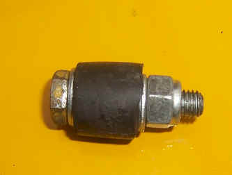
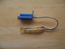
Make up a sealing plug with a M6 bolt and a bit of fuel hose. Tightening the bolt will expand the hose to provide a good seal (see below).
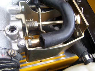
Remove this pipe from the plenum chamber, and insert the sealing plug to make an air tight seal. Refit the pipe to prevent air reaching the air control valve.
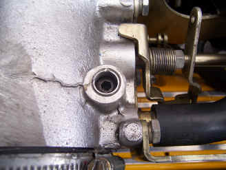
Base idle adjustment is made by turning a set screw that's normally hidden under a tamper-resistant plug on the Throttle body. To access the screw, first drill a small hole (typically 1/8") in the tamper-resistant plug. Thread a sheet metal screw into the hole, and then pry the screw & plug out together. The main throttle butterfly is fully closed at idle, so there is a air bypass screw adjustment on the top of the plenum chamber that works together with the stepper motor. The screw adjustment is factory set, and sealed with a cap, and normally will not need adjusting. To set this setting start the car (it needs to be warm) and adjust the screw for a tick over of about 600 rpm. Once set the rubber bung can be removed from the feed pipe, and the stepper motor should lift the tick over to around 800 rpm (This speed is set by a setting in the fuel map, and is not manually changeable). If you are running without a stepper motor a base idle of around 900 rpm will suffice.
Inside the ECU
As the ECU has been around for quite a few years there have been some changes. The most important one was around 1990 when the PCB layout was changed, together with the way the fuel maps worked. This means fuel chips between the two versions are NOT inter changeable. On the early type the square chip next to the fuel map chip will be marked with the number MVA5033, and the later type will be marked MVA5033-KA. Some ECUs have the fuel chip covered with a plastic cover, that can be removed by part crushing it across the sides so it unlocks from the chip carrier.
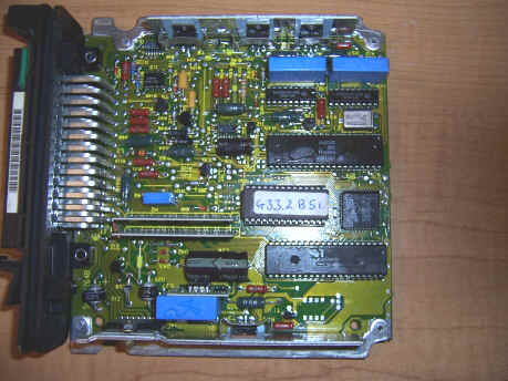
There are no user serviceable parts, apart from the fuel chip (shown here as G33.2.b51). Its worth checking for dry solder joints, and more importantly check the pins in the main connector for corrosion, or any pins that have been pushed back.
Fuel Maps
The fuel map is held in a 27C128 or 27C256 type Eprom, dependent on the revision of ECU. Although the 27256 device has twice the storage capacity of the 27128 type device, it appears that you can still put the smaller device in place of the larger one as the highest address line is not used. The device itself contains multiple maps, such as catalyst, non catalyst, limp home, and some country specific ones for particular fuels. These are selectable with a plug in tune resistor found under the passenger dashboard. Changing these values alters the base address used to find the relevant fuel map in the Eprom. On the early 14CUX units the Eprom device is soldered in, and does not have the classic quartz window in the chip. Later units have a plug socket, and plastic cover over the Eprom. To reprogram the early units the old device has to be cut out and the chip legs carefully removed one at a time. Its almost impossible to get the chip out in once piece, so once you have started there is no going back! Its recommended that a “turned pin” type chip socket is soldered into the board as these have better electrical connections in the harsh environment of a cars foot well where the ECU lives. After many years the method for reprogramming the 14CUX has been cracked and is covered here
ECU Trim Values
There are many values that can be altered such as the upper rev limit, the amount of cold start fuel supplied, the point at which the system goes open loop, plus the overall fuelling levels of the map.
Memory map is 64K bytes big (16 address bits), and the program/calibration chip sits at address range C000-FFFF. Tune data is at the beginning of the chip, from chip address 0000-07FF. Program (but not entry point) officially starts after at 800h, although there are several 'hidden' calibrations (like overriding rev. limit) just after 07FF. Actual program entry point can be found from the reset vectors at the top end of the chip with reference to the 6803 processor data sheet.
Fuel maps are 2-axis maps 16 by 8 sites, speed versus load with 16 speed sites and 8 load sites. Load is calculated from the AFM reading by a formula which includes a scaling factor from the engine speed. This means that (maybe) 30 litres per second could give max load (site no.7) at 1000RPM, whereas it could take (maybe) 150 litres per second at 5000RPM to give the same load site. (Those figures are illustrative guesses!). Speed axis is a simple set of breakpoints with RPM. The breakpoints I believe have always been the same as follows:
| Site | 0 | 1 | 2 | 3 | 4 | 5 | 6 | 7 | 8 | 9 | 10 | 11 | 12 | 13 | 14 | 15 |
| RPM | 200 | 480 | 620 | 700 | 780 | 900 | 1100 | 1400 | 1750 | 2000 | 2700 | 3100 | 3750 | 4100 | 4752 | 5502 |
If you can adjust whatever you use to view the chip data to display 16 columns, the first map should be glaringly obvious. Since the data groups are not on 16-byte boundaries the others may be less so however, but the maps are almost identical so should be spottable.
Directly after each map is the scaling factor applied to it, a 16-bit value usually of the order of (hex) 6590 or maybe 61AB. Fuel maps usually start with several instances of the same value, often (hex) 14 or 21. Each fuel map is at the start of a section of tune data applicable to that tune (as determined by the tune resistor) which extends down to the start of the next fuel map. Many things like acceleration enrichment, order of accessing analog inputs, cold start maps and other stuff are included on a per-tune basis, but some stuff found in the first (tune 0) area applies to all. There are six areas including tune zero. All are exactly the same size except zero. Individual map locations appear to be:
| Map Location | Wire Colour | Tune Resistor | Application |
|---|---|---|---|
| x0000-0x007F | N/A | N/A | Tune 0 (limp home) |
| 0x0267-0x2E6 | Red | 180 | Australian 3.9 non cat |
| 0x0379-0x03F9 | Green | 470 | UK non cat |
| 0x048B-0x050B | Yellow | 910 | |
| 0x059D-0x061D | Blue | 1800 | Gulf States 3.9, or Europe & UK 4.2 non cat |
| 0x06AF-0x072F | White | 3900 | Europe & UK 3.9 (or 3.5 Disco) catalyst |
Aftermarket Fuel Chips
Over the years there have been many improvements over the Lucas mapping, plus bespoke mapping for tuned engines, and chips will vary in price from around £70 to £400. There are some Rover V8 tuners who will gladly sell you a "power chip" for a lot of money that is simply a copy of some ones else modified fuel map. The really important thing to realise, is fuel maps are set for a particular engine set up, so don't believe for a moment that plugging in a "300 bhp" chip into a 3.9 will suddenly generate more power, it’s far more likely to make the car run badly. Also don't believe that fitting a chip from a bigger or more powerful engine will improve the power, and there are no hidden "power maps" held within the Eprom. A good mapper will always ask for your exact engine specification before supplying a chip, and may modify both catalysts and non catalyst maps for your application. In an ideal world the A.F.M measures the air mass, then all you would have to do add an appropriate amount of fuel for any given engine load, so "one chip would fit all", but this is not the case, and the whole point of mapping is to get the engines fuelling requirements to match the cam profile, plus inlet and exhaust as closely as possible, as these control the engines efficiency at different RPM's. An AFM based system is pretty good at compensating for moderate engine modifications, so don't assume if you say alter the inlet trumpets you need a re-chip. Also the catalyst fuel map is pretty good a compensating for moderately incorrect mapping, but if you still think you need a re-chip, then first you need to make sure the whole fuel injection and ignition is working as it should, then take the car to a rolling road for mixture checks under load to see if there is a problem, before assuming the stock set up needs modifying. If you want to try re mapping yourself all the tools are now available based on the freeware program Tuner Pro. Tuner Pro requires an "xdf" file for the specific locations of the various parameters you want to change, and now the 14CUX has been reverse engineered this makes the mapping process much more understandable. All covered in depth here.
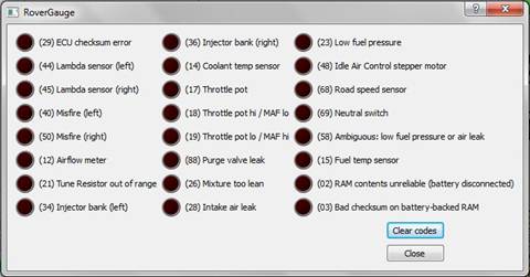
Basic Fuel Injection Fault Display
The Range Rover setup allows an ECU warning light to come on if the correct air fuel ratio cannot be maintained, but is not enabled on all ECU fuel maps and it appears that only after market and maps supplied to the American market have this useful function. Failure in one of the input sensors will cause the warning light to illuminate, and the ECU will drop into the "get you home" mode. This causes the ECU to default to a "fixed fuelling" map, that can run without sensor inputs. This will limit the cars performance and tends to run a bit rich, until the fault can be cleared. The fault codes are only generated under severe fault conditions and are far from accurate, so don't always believe what they tell you.
The fault display has to be plugged into a socket in the wiring loom above the ECU that provides two-digit diagnostic codes. The Lucas units are for sale in the USA (like eBay ) as all US Range Rovers are fitted with them as standard on the second hand market. Part number is PRC17EM or Range Rover OBD. There is an aftermarket one available from Steve Heath Engineering here. There is normally a socket in the wiring loom near the fuel pump relay that the fault code reader plugs into but there are some latter looms that the wiring and socket has not been included at all so extra wiring to the ECU connector is needed, details here.
For cars without Lambda sensors the fault codes are limited, but can at least point you in the correct direction. To reset the unit after a fault has occurred, disconnect it from the battery. If multiple faults exist, the display shows the one that the ECU thinks is highest priority. Higher priority faults need to be "cleared" before lower priority faults will be displayed. A "blank" (dark) display usually indicates there are no faults.
Use this procedure to clear faults:
- Switch "on" the ignition
- Disconnect the serial link mating plug, wait five seconds, and reconnect
- Switch "off" the ignition, and wait several seconds
- Switch "on" the ignition. The display should now reset
Note: It should either show a lower priority fault code or appear dark.
Note: Fault code "02" will appear after a disconnected ECU is reconnected. Simply switch on the ignition to clear the display.
Fault Codes
02 ECU Supply has been disconnected
Normal code to get after ECU has been reset. May indicate supply problems if ECU has not been reset recently. Code will be cleared if the ignition is turned on for 30 seconds or so.
03 Data corrupted. Corrupted data in ECU. Reset ECU and test drive again.
12 Airflow meter out of range Possible faulty airflow meter or connection/wiring fault.
14 Coolant thermistor out of range. Possible faulty coolant thermistor or connection/wiring fault.
15 Fuel thermistor out of range. Possible faulty coolant thermistor or connection/wiring fault.
17 Throttle pot out of range. Possible faulty throttle potentiometer/incorrect setting or connection/wiring fault.
18 Throttle pot output too high with low airflow. Major air leak between airflow meter and intake plenum. Possible faulty airflow meter or throttle potentiometer or wiring/connections to either.
19 Throttle sensor output too low with high airflow. Possible faulty airflow meter or throttle potentiometer or wiring/connections to either.
21 Tune resistor out of range Tune resistor has become disconnected/damaged
23 Low fuel pressure. Possible faulty fuel pump/blocked filter or faulty fuel pressure regulator. VALID FOR CAT CARS ONLY.
25 Misfire at full load. A misfire has been detected while engine under heavy throttle and during high airflow meter readings. Check coil/plugs/leads/ distributor and ignition module. Code means that lambda sensors have detected a rich condition under load. Also see codes 40 and 50. VALID FOR CAT CARS ONLY.
28 Air leak. Air leak around intake plenum. Check all hoses/injector seals etc.
29 Checksum error. ECU fault. Try resetting ECU and test driving again. If fault code returns ECU may be faulty. NOTE – any other codes generated should be ignored.
34 Fuelling fault in nearside injector bank. For cylinders 1-3-5-7 Possible injector, lambda sensor fault or wiring/connection fault to either. Blocked injector(s) or air leak at injector/inlet manifold. VALID FOR CAT CARS ONLY.
36 Fuelling fault in offside injector bank. For cylinders 2-4-6-8. Possible injector, lambda sensor fault or wiring/connection fault to either. Blocked injector(s) or air leak at injector/inlet manifold. VALID FOR CAT CARS ONLY.
40 Misfire on nearside bank. Misfire on 1-3-5-7 cylinders only. Nearside lambda sensor has detected a fault (or fault in lambda sensor circuit). VALID FOR CAT CARS ONLY
44 Offside Lambda sensor out of range. Possible faulty lambda sensor or wiring/connection fault. See section 5 below for check. If in conjunction with code 45 then suspect lambda heater circuit. VALID FOR CAT CARS ONLY
45 Nearside Lambda sensor out of range.Possible faulty lambda sensor or wiring/connection fault. See section 5 below for check. If in conjunction with code 44 then suspect lambda heater circuit. VALID FOR CAT CARS ONLY
PDF's from Roversnorth - Thanks guys.
48 Stepper motor fully open below 500rpm or fully closed above 750rpm. Possible faulty stepper motor or wiring connections. Stepper motor needs cleaning/is jammed. Incorrectly set idle adjustment screw. Incorrectly set throttle butterfly. Misfire or rough running because of other faults.
50 Misfire on offside bank Misfire on 2-4-6-8 cylinders only. Offside lambda sensor has detected a fault (or fault in lambda sensor circuit). VALID FOR CAT CARS ONLY
58 ECU cannot distinguish between codes 23 and 28. Fault maybe either due to code 23 or 28.
59 Same as 58 or fuel thermistor out of range. Documentation seems to vary here. Code either means same as 58, or faulty fuel thermistor or wiring/connector fault.
68 Road speed sensor too low at medium rpm and high airflow. Possible speed sensor or wiring/connection fault.
88 Power-up check/purge valve fault. Sometimes shown on power up (CAT and NON-CAT CARS ) or could also indicate purge valve fault with carbon canister system. (CAT CARS ONLY)
Further Diagnostics
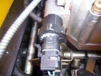
There is a 5 pin Lucas TTS connector that pokes out of the loom that connects a basic OBD1 (On board diagnostic) port on the ECU. This allows both sensor data to be read, fault codes, mapping data, and even allows you to control hardware functions of the ECU by sending the required commands.
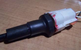
The serial OBD1 connector found poking out of the loom, known as a Lucas TTS 5way
The following sensor data can be read live:
Air Flow, Throttle Voltage, Lambda A, Lambda B, RPM, Injector Pulse, Purge Monitor, Coolant Temp, Stepper Position, AirCon Monitor, Front Screen Monitor, Gear Switch, Road Speed, Fuel Temperature. Fuel Map locations. Originally this could only be read by the expensive Rover Test book system, and the Lucas Lazer reader, but more recently other tools have become available to the home mechanic.
These are:
1) The Hawkeye diagnostic
This handheld unit gives basic sensor data and fault codes.
2) The Steve Heath ECUmate
Steve Heath ECUmate that also reads the OBD serial data for the various sensor inputs, like the Hawkeye, plus some mapping information, but the big difference is it can also send signals back into the ECU to allow manual control of the fuel pump and stepper motor, as the stepper is frequently blamed for an irregular idle, when in fact other things are to blame. This is a good unit to keep in the boot incase of breakdown.
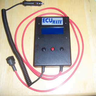
Download the manual here
3) Rovergauge: PC based diagnostic
This
superb bit of software is provided as freeware By Colin Bourassa and
Dan Bourassa, dedicated Rover V8 fans, who have progressed the
understanding of the 14CUX forward further in the last couple of years
than the previous 20, making the information freely available. Its
downloadable for both the Windows platorms and Linux.
We all thank you gents!
There are two posts on Pistonheads covering its development, and more recently the ability to re-map the ECU.
RoverGauge is a graphical display and diagnostic tool that reads runtime data from a Lucas 14CUX engine management system. The 14CUX was paired with the Rover V8 engine in Land Rover vehicles from 1990 to 1995, and also in sports cars made by low-volume automakers (TVR, Morgan, etc.) throughout the 1990s. This software uses Google Project Hosting to store its code (and it depends on another piece of software that Dan wrote, libcomm14cux, which has its own Google Project page):
http://code.google.com/p/rovergauge/
http://code.google.com/p/libcomm14cux/
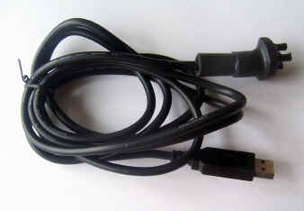
You need to make up a USB to serial adaptor (that needs to be programmed) and make up a plug with some resistors to fit the Lucas TTS connector, and details are on the web sites listed above. The Lucas 5 way TTS plug is now obsolete, so Ive had to make some suitable connectors from scratch, and I can supply ready made cables at £35 if you dont want to make your own with all the required software and 14CUX manuals on CD. Drop me a mail if you want one: Mark@blitzracing.co.uk
Before running RoverGauge on a PC, its is necessary to install the software drivers to run the USB- to serial converter cable as if you fail to do this Windows may not recognise the USB device as a serial com’s port.
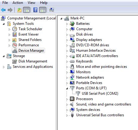
Now go to Device manager in Windows: It can be found from a right mouse click over the “computer” icon either in the start menu, or on the desktop, and select manage. Device manager should be listed under system tools in the left hand column. Double click on this to display a list of the hardware devices on your computer.
Now plug in the USB cable and watch the hardware list as windows “plugs and plays”, the list of hardware devices should “reset” as the new device is now recognised. There should be a category for Ports (Com's and LPT). Expand the ports category, and the USB serial port should now be listed together with its Com port number - make a note of this number for configuring RoverGauge. In this example below it’s seen as Com2. If by chance there is more than one USB port listed, right mouse click on each port and note the manufacturer under “properties”. The serial cable will be the one marked FTDI.
RoverGauge can now be started and configured. It can be run directly from the CD, from the RoverGauge program folder – RoverGauge, or if you wish copy the whole RoverGauge programs file folder onto your PC, and it can be run from there. You must copy the whole folder for the program to run, and the RoverGauge program can be run from directly from inside this folder. Once the program has started (it will take some time from CD) go to “options”- edit settings - to display the serial device name;
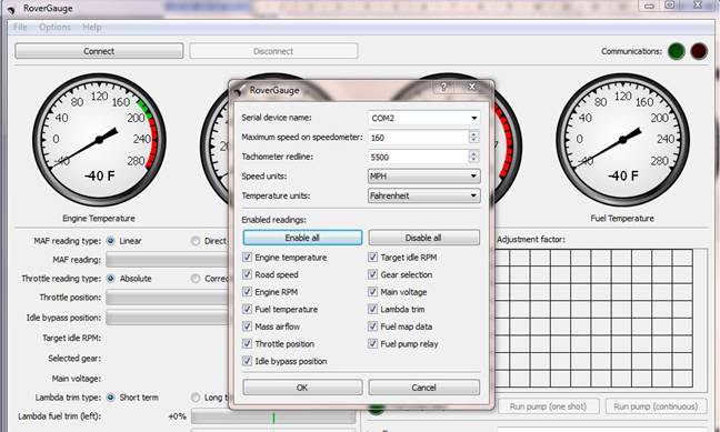
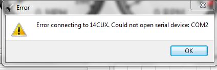
Now enter the serial device name you noted from device manager, followed by “OK”. The serial device name may not appear in the drop down box, so it simply needs entering manually in this case. You can now do a simple test to see if RoverGauge can communicate with the USB device, by using the connect button. It does not need to be plugged into the ECU loom at this point. If nothing happens its likely working OK, otherwise it’s likely to error if the basic com's settings are wrong:
You can now plug the USB cable into the 14CUX diagnostic port 5 pin TTS connector This will be found poking out of the loom near the ECU, On the TVR its behind the panel in the passenger foot well, On the Range Rover its under the drivers seat. It should have a grounding plug in it, that needs removing first and is best done with the ignition OFF. Dont confuse this with the BLACK Air suspension TTS connection on AES Range Rovers. It wont work !.
Align the 3 socket connectors with the pins in the TTS connector and the outline of the diagnostic plug should align with the plastic housing of the TTS connector, and push the connector home for a good connection.
The ignition can now be turned on, and then use the connect button on RoverGauge to establish communications with the 14CUX. The red connection light in RoverGauge should then go to green, and immediately the gauges should start to read the sensors with just the ignition on. The red light will be lit if the 14CUX is off, if the serial cable wasn't wired correctly, or if the wrong COM port was chosen. There are also two indicator lamps on the USB plug- red and green. The red one (transmit) should pulse as RoverGauge requests data from the ECU, and the green one (receive) should pulse as the ECU sends data back- this is pretty much instantaneous. If only the red one pulse’s there is not a connection with the ECU, so carefully check the plug is inserted correctly, and that a pin has not misaligned. If the Red one does not light there is a configuration issue with the PC or hardware failure. Occasionally both lights will light, but no data will be displayed on RoverGauge. This happens when the simple data handshaking on the 14CUX gets in a twist. If it cant be cleared with a disconnect and reconnect from RoverGauge, then try removing and re-plugging the 14CUX connection with the ignition on and RoverGauge in a connected state, but only if all else fails.
The main window shows the following:
- Coolant/engine temperature
- Road speed
- Engine RPM
- Fuel temperature (also used as an indicator of under-bonnet temperature)
- Tune- the current version of software tune in the ECU Eprom
- MIL- an indicator that shows a fault status is logged
- Communications- green or red for good or bad communications to the ECU.
- In addition to this, the display will show the throttle position, the reading from the mass airflow sensor, the neutral switch reading (indicating whether an automatic transmission is in gear), the main voltage, stepper position, target idle status, fuel map data, and lambda trim values for the left and right bank of the V8.
Options Menu
Show Fault Codes
Options menu- Edit settings
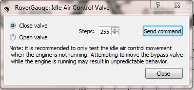
Options menu - Idle Air control
Testing for unstable idle issues
There are frequently idle control issues, and several conditions have to be met for the ECU to switch into an idle control status. The ECU monitors the throttle pot voltage, to see if the throttle is shut, and if the speed sensor input is zero to see if the car is stationary, and if both conditions are met the stepper motor is set to control the idle. On both a cold engine or a car that is moving the idle is held slightly higher than normal, so once in idle mode the ECU will drop the tick over to a value programmed in the ECU fuel chip. The ECU applies a short burst of pulses to the stepper to reduce the idle, and then waits a couple of seconds to allow the engine to stabilise. If the idle is still high, it applies another burst of pulses until the desired RPM is reached. This will be seen with the idle status lamp going green on the RoverGauge main display when all the correct conditions are met.
A speed signal or high throttle pot will prevent the ECU reaching its idle status- and is a common problem on some TVR’s that use a speedo conversion box to generate a fixed car moving signal above 3mph (or so). Poor circuit design and poor earthing allows the unit to trigger when the car is still, and will be seen as a speed reading on the main RoverGauge speedo even when the car is stationary. This will lead to an erratic high idle.
Problems with the car stalling can be down to a sticking stepper motor or stepper motor housing chamber being full of carbon and oil, or incorrect base idle. Instructions on the procedure for setting the base idle can be found in the 14CUX fuel injection manual on the accompanying CD. The base idle is officially set to 525 RPM with all the air feed blocked off to the stepper motor, and then when the stepper is working it supplies enough additional air to lift the idle to the required value. Its pretty much impossible to get a tuned Rover V8 to run at 525 RPM to set the base idle, so it can be simply set as low as the engine will allow before it dies. A correctly set base idle will give a stepper motor reading of around 30-40% to show the stepper is in its normal airflow range. Values of 0 % or 100% show the stepper is outside its correct range, so other factors must be a affecting the airflow into the engine. This will eventually lead to a fault code being registered by the ECU.
To check the stepper motor operation on a running engine, allow the engine to idle then apply a test burst of 30 or so open pulses to the stepper motor to allow more air. This should lift the idle by a few hundred rpm, and then within a few seconds the ECU should pull the idle back to its required setting if the stepper is moving correctly. If it fails to correct the idle, the stepper may be sticking, and even if the stepper position has changed on RoverGauge, the ECU has no way of knowing if the motor is actually moving. The ECU does not appear to correct for a low idle once its been set by RoverGauge, so if the stepper motor is moved manually in a closed direction the engine will simply die as the airflow is reduced. The ECU also has a couple of inputs that lift the idle when a heavy electrical load such as a heated windscreen is switched on, or when an auto gearbox is put into drive. This help prevent the idle dropping too low as the engine load increases.
Some other factors that affect the idle can be air leaks in the plenum area that can cause a shift in mixture as the engine reaches idle when the throttle plate is shut, dirt around the throttle plate causing it to stick open, or misfires that cause the idle to drop faster than expected in the ECU programming. A failing A.F.M’s can also lead to over fuelling at low RPM and poor idle.
Interpreting the sensor and fuel map readings
Fuel Maps
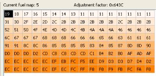
The fuel map displayed by the software is the map currently in use by the vehicle. Note the map number with the engine running, as occasionally the wrong map is displayed on power on. There are 3 maps that are commonly seen on UK / USA vehicles:
Map 0 (Limp home tune)
This means the ECU has picked up a fault code and is running in limp home mode. There may also be a fault code also held saying what has failed. (See below). It may be cleared by resetting the fault codes, or unplugging and re-plugging the ECU to remove the power. If the error reoccurs, then the fault condition is still present and it will stay on map 0
Map 2 (green tune)
This is the non catalysts fuel map, and is the best to use if the engine does not need to be emission compliant (or has no catalysts fitted) as it allows a wide range of air fuel ratios to be used for both best power and economy. The map is non adjusting, so it has to be the correct map for the engine. Frequently only one map is modified by tuners, so don’t assume the map will be correct if switching tunes. Lambda signals are set at an artificial “0” point and ignored.
Map 5 (white tune)
This is the emissions compliant map used in US and UK vehicles fitted with catalysts. This clamps the mixture at lambda 1 below 3400 rpm or 2/3rds throttle by trimming the mixture dependent on the Lambda signals from the exhaust.
Other maps are used in other areas of the world dependent of local emission laws and fuel quality, and hence the engine compression ratio. Map selection is set by changing the tune resistor found poking out of the loom. The colour of the insulated wire refers to the map type such as white (catalysts) or Green (non catalyst). This example is the white tune.
Some ECU’s are programmed to prevent the maps form being switched, plus the resistor will be missing from the loom. This will default to the white tune catalyst map. This function is held within the Eprom, so only changing this will restore the ability to switch maps with the required resistor.
Map Layout
Each row represents a range of engine speed, and each column represents a range of engine load. Each cell in the grid shows the raw fuelling value for that combination of engine speed and load, and the cell background is coloured to provide a quick visual indication of the fuelling at that position in the map. Engine speed increases left to right, and engine load increases top to bottom. The table below shows the stock Range Rover / Land Rover RPM bands. Aftermarket and tuned applications will have the RPM range increased, and will be shown on RoverGauge in the row above the current fuel map.
| Site | 0 | 1 | 2 | 3 | 4 | 5 | 6 | 7 | 8 | 9 | 10 | 11 | 12 | 13 | 14 | 15 |
| RPM | 200 | 480 | 620 | 700 | 780 | 900 | 1100 | 1400 | 1750 | 2000 | 2700 | 3100 | 3750 | 4100 | 4752 | 5502 |
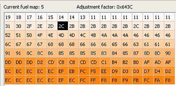
The black block will move around showing the specific fuel load point the engine is using when running.
Adjustment factor
A value applied to mapping data dependent on engine size.
Throttle position
This has two values- absolute and corrected. For test purposes we want the corrected range to represent the percentage change the ECU sees between a fully closed and full open throttle position.
So a throttle position sensor that is within the correct range will show:
| Throttle shut | 0.085-0.545v | 2% to 10% |
| Throttle fully open | 4.2-4.9v | 84% to 98% |
The absolute value shows the effect of the voltage offset applied to the throttle pot in the throttle closed position. This is there so when the ECU does a sensor check it picks up this voltage to show the throttle pot is connected, (otherwise it throws a fault code) and it also allows the ECU to calibrate the expected throttle pot range automatically. The output voltages need to be in the above throttle shut range for the self calibration to work.
Typically a throttle pot that is adjusted correctly will go from 5% to 97% corrected range. It should not drop below 2% minimum or the ECU may throw a fault code saying the throttle pot is out of range. The display bar should move slowly and smoothly as you operate the throttle, as if it jumps around, you have dead spots in the potentiometer travel, and the throttle pot should be replaced. The fixing holes in the throttle pot can be elongated with a file if the required range cannot be met, but is not normally required.
A.F.M. (Air Flow Meter)
The AFM scale has two settings, linear and direct. The direct reading is unmodified from the AFM voltage output, that has a very large voltage change for changes in low air flows, but the voltage change range reduces as the airflow increases as a logarithmic response. The Linear reading shows the airflow volume the engine uses to calculate the engine load after the logarithmic response has been recalculated by the ECU programming.
For practical readings the direct airflow is the best option, as this shows the biggest voltage range near tick over so its easy to read and see if the AFM is within spec’.
Typically the AFM voltages can be measured at idle against a 5 volts reference as:
1.6 volts for a 3.5 litre engine = 32%
1.62 volts for a 3.9 litre engine 32.4 %
1.75 volts for a 5 litre engine =35%
These figures will vary if the idle is not standard (i.e. re-chipped) or the car is running badly and the idle is unstable. Normally when an AFM fails it will be a long way out- say 40% at idle.
Full power readings cannot be taken due to the ECU stops reporting sensor data at high RPM due to lack of processing power.
Speed readings
These should be equivalent to the speed readings on the speedometer on vehicles that have the chopper disk system to provide the speed signal. This does not apply to TVR’s however fitted with the Ford gearboxes. Here TVR put a small box of electronics under the dashboard called the speedo calibration unit that simply detects if the car is moving, and then once a speed of about 3mph is reached the unit produces a fixed pulse train to represents the cars speed of approximately 30 -50 mph that does not change, so it gives simply a go or no go reading.
Lambda trim values
In closed loop the ECU will constantly trim the mixture to keep the car emission compliant. This is the amount of added or reduced fuel to keep the catalysts cycling as they should. The reading from RoverGauge is what the ECU is applying to correct the mixture, NOT what the actual lambda probes are producing as a signal. So a high lambda voltage of over 1 volt represents a rich mixture, so the ECU will remove fuel trim to make the mixture lean enough to switch to 0 volts and visa versa.
Rover gauge can read either both long and short term fuel trim by selecting the Lambda trim type.
About Long term fuel trim
This is a “base line “ value applied to the mixture by the ECU to reach lambda 1 and is referred to as the long term fuel trim. This is set with a warm engine (at least 90’C) and stable idle, and no throttle input. The ECU then has a stable platform to work with, and will alter the long term trim value until the mixture is correct depending on the average voltages read back from the Lambda probes. This value is then stored in battery backed up memory, so it’s already set next time the car is started. This value will only change slowly during the tick over period, if at all once set. A value of 0 %, or mid point represent a perfect fuelling condition, and any value below 100% is acceptable although the nearer to 0 % the better. The left and right trim values for each side of the V8 may be seen to differ without causing any problems. If the long term fuel trim show very high levels of correction, or hits either + or - 100% fuel trim, then either a sensor input is wrong such as temperature or AFM, a fuelling condition has occurred such has over high or low fuel pressure, or possibility the basic fuel map is not suitable for the engines requirements. Incorrect engine timing will also cause incorrect trim values.
About short term trim
Then once the car is moving a small amount of fuelling correction is available as short term fuel trim. This alters all the time depending on the signal from the Lambda probes to keep the mixture correct to keep the emissions low and the catalysts functioning correctly. This will be seen as a constant shifting level of trim cycling at between once to twice a second depending on engine RPM, but like the long term trim should not sit at either + or - 100% for extended period.
It is also important to note that misfires get picked up as a lean mixture by a lambda probe- so the ECU will try and compensate by adding short fuel trim. This will not resolve the misfire so the ECU may simply sit at + 100% fuel trim until the misfire is resolved.
Water temperature
This should follow the cars dashboard temperature gauge, and can be set to ‘C or 'F in the options menu.
Fuel Temperature
This can be used as a rough gauge to engine bay temperature and can be set to ‘C or ‘F in the options menu.
Throttle bypass valve (stepper motor) position
This shows the position the ECU “thinks“ the air control stepper motor is currently in, and will be seen changing to keep the idle stable to try and reach the target idle RPM (green lamp displayed) as set in the fuel map programming. As there is no feedback from the stepper motor, the position may not be correct if the stepper has become stuck, so the idle will not be controlled correctly. There is test in the options menu to move the stepper to prove its working. If the motor has been removed from the plenum it would be possible to drive the plunger out fully to the point it would ping out of the motor and get lost, so proceed with caution. By default the stepper is always opened fully (180 steps) before a cold engine is started.
Gear position
This input is used for auto gearboxes, as the idle needs to be raised by the ECU / stepper to compensate for gearbox drag when the car is put into “drive”
Main Voltage
This is measured by the ECU as it affects the injector opening times, so has to be compensated for as the voltage varies.
RPM
This is derived from the coil trigger from the ignition amplifier, and is fed to the ECU via a 6.8 k resistor found in the loom. Unstable readings would imply a bad trigger signal is coming from the coil.
Fuel pump status and control
There is a green dot display showing that power is being fed to fuel pump relay (that also supplies the Lambda probe heaters), together with the option to manually pulse the pump (as in “ ignition on” pulse) or put the pump on permanently. This can be used to track down relay or pump issues, or do fuel pump pressure tests without the engine running. Fuel line pressure should be 3 bar (37 psi) with the engine static and the pump running.
Advanced features
The "Save PROM image" feature (in the "File" menu) will read the entire 16KB to 32kb image from the 14CUX's EPROM and save it to a file. If you wish to save the file name it as an xxx .bin file to signify it’s a pure binary file. The program does not default to this file format. The Binary file can then be read either in its raw form with a hex editor program, or an engine mapping program like WinOls.
There is also a data logging facility in the main display that will write to a basic text file. It firsts list the sensor values in order on the first line, and then displays the value of each of these sensors as the ECU reports them. The log file is written back into the RoverGauge folder in a sub folder called logs. RoverGauge needs to be run from the hard drive to allow for it to be written. NOTE. The ECU’s limited processor power means some sensor data may not be available to the serial port as the engine RPM increases. So use the settings in the options menu to turn off un-required readings to improve performance.
To convert the log files into a readable file:
1) Copy the data into a word document
2) Use the Edit- replace command to replace the, (comma) with a tab. You need to use the extended edit menu, replace, special, tab character.
Then copy the text from Word into Excel, so the tab charater puts each value into a different cell. You will need to elongate the cells to match the headings.
ECU urban myths
Over the years various myths have risen up about this ECU, and not all of them are true.
Examples are:
You need to drive for 20 minutes to stablise the mixture after a ECU reset.
Untrue- it takes place in about 2,5 minutes seconds at tick over on a warm engine.
You need to reset the stepper motor if you remove it.
Untrue. The stepper is reset every time the ignition is cycled off, but
sending 200 pulses into a 180 step motor, so it will always reach
"home".
You need an ECU reset to clear fault codes and reset the mixture.
True - The ECU contains no volatile memory, so a 30 second power off
(as in unplug it or disconnect the battery) will remove any fault
codes, and any stored fuel base settings. These will be re established
once then engine is running at tick over.
The fuel map “stops” at 5400 rpm.
On the standard Range Rover fuel map does not increase the amount of
fuel above 5400 rpm, but simply carries on fueling as if the engine was
still at 5400 rpm. This can be overcome with aftermarket maps.