TUNING
Even at its best in the G33, the 3.9 Rover V8 only produces around 205 BHP even when correctly chipped. At just over 50 BHP per litre there is some fairly easy extra horsepower to be had. The standard engine is setup to produce lots of low end torque, with peak power at a low 5200 RPM.
You need to decide if:
- If you just want to modify the inlet manifold, trumpets, and exhaust manifolds
- If you want to "blueprint" the inlet and exhaust ports having removed the heads
- If you wish to remove the Timing cover and drive gear to fit a different cam
I will cover the various options in terms of complexity.
Shortening the inlet trumpets
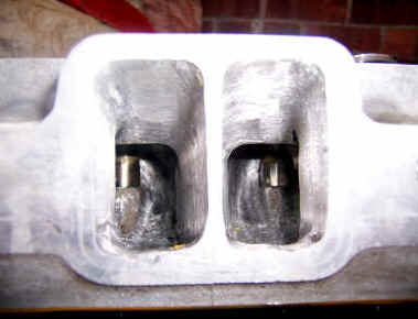
The top of the air intake trumpets are very close to the top of the plenum chamber, and as the intake velocities increase this causes a restriction. The use of long Trumpets also affect the point maximum torque occurs, and are set up to provide this a low RPM by having a long narrow inlet tract. Shortening the trumpets clears some the restriction and supposedly moves the power band up the RPM range, which is fine in a lightweight G33.
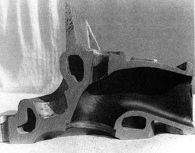
This cutaway shows just how close the standard trumpets are to the top of the plenum chamber.
The top of the Plenum chamber needs removing to expose the trumpets, removing the various pipes and wires as you go. Once the trumpets are exposed, I would recommend that a paper towel is forced down the trumpet into the inlet tract below to prevent muck dropping into the engine when the trumpet is removed (unless you want to remove the inlet manifold as well.-see below). Then using a blowtorch gently heat a trumpet at a time until the glue loosens and the trumpet can be rocked side to side a bit and pulled free with a mole grips or the like. Once removed you need to cut around 15-25mm of the base. It its best to use a lath, but as the trumpet wall is thin a mandrel of some sort is advisable to fit neatly inside the trumpet to stop it crushing in the lath jaws before its cut down. You can do it by hand with a Junior hacksaw, and use tape to mark the cut line, but its difficult to keep everything square and neat.
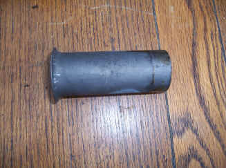
A removed trumpet before machining
Once the trumpets are cut down they can be re-glued back in place (having removed the paper towel) with a high temperature Loctite or epoxy (like JB weld).
A standard trumpet base alongside my cut down one. I stuck to just 15mm that will allow the extra clearance above the trumpets, without affecting the torque curve that much although up to 25mm can be used.
Keeping the Inlet Charge Cool
The Range Rover inlet manifold throttle body has a hot water preheat fed from the water pump. Although you might need this in sub-zero temperatures, its really not needed in the G33. At low temperatures the manifold is heated to prevent fuel condensing in the inlet tract, but it also has the adverse effect of heating the air and reducing its density. You may have noticed the car performing well on cold damp morning, and the colder air is the reason for this. The simplest thing to do is simply disconnect the two pipes that provide the preheat just under the butterfly valve in the Plenum chamber. The pipe can then simply be looped between the water pump and inlet manifold take off points.
Another modification involves fitting a thermally insulating plate between the inlet manifold and the trumpet base and are commercially available form some V8 tuners for around £50. This prevents the heat from the engine traveling up into the plenum chamber, and I have seen figures quoted of an extra 10 BHP when the engine is hot. There is a problem with the G33, that the insulation plates raise the plenum chamber by up to 10mm, and this means it wont fit under the bonnet ! The aftermarket plates are made of Tufnell. Blank sheets available on eBay for a few pounds.
Exhaust Manifolds
You are very restricted on your choice of exhaust manifolds on the G33 due to the very tight engine bay and steering column. Bespoke systems are pretty expensive, and I honestly believe that the cast manifold can be made to perform reasonably well with some modification. Its generally accepted that the standard exhausts will restrict the car to no more than around 240 bhp, but as usual a little inspection will show why. The narrow exit section of the manifold is considerably smaller than it needs to be, and will be the most restrictive point for the exhaust gas. The short cast passage from the port exit is the smallest point and can be opened up significantly. The remaining manifold to the down tubes are considerably larger, and will present less restriction, although there is a nasty step where the cast manifold joints the down tubes. So out with the rotary files and match the casting to the gasket and remove some pretty obvious casting lumps from within the manifold entry area. Its quite easy to achieve an increase port area of 25% without compromising the gasket seal, but beyond this the wall thickness is likely to become too thin to seal effectively. You can remove a bit more further into the port as the casting is pretty thick. The step where the manifold meets the down tubes also need to be blended out. Cast Iron is not a hard material and the total job took around 2 hours.
If you are thinking of the tubular manifold route there are a few considerations. To make the most of negative pressure created in the header pipes after the exhaust pulse has passed from one cylinder, the next cylinder to exhaust needs to feed into the same pipe. On the V8 this leads to some seriously complex plumbing that is simply to big to fit the available space. Also ideally all the header tubes should be the same length, and on many systems this simply does not happen as the pipes invariably feed towards the rear of the car, so the front pipe is always longest. Most systems have primary headers of at least 1 1/2" that helps to reduce back-pressure, but take this too far and some of your inlet charge will disappear down the exhaust at the point when both the inlet and exhaust valves are open at open at the point of overlap. Basically a couple of hundred pounds spent in a tubular system may not release any significant gains over a ported cast manifold.
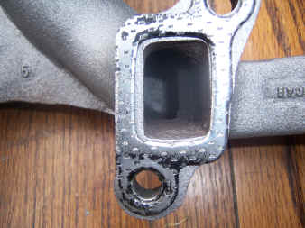
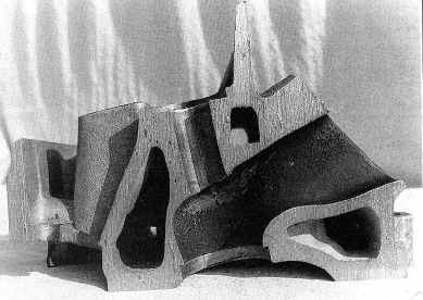
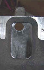
Standard cast exhaust manifold inlet. Open it up to match the gasket.
Job done
Manifold exit now matched to the down tube entry
Removing the Inlet Manifold for Porting
You need to remove the plenum air pipes, and throttle cable and the hex head screws to free the plenum chamber cover. Then having removed the plenum chamber cover, the bolts that hold the trumpet base to the inlet manifold need removing. It SHOULD now be possible to lift the lower trumpet casting away from the manifold. It’s more likely however that it will not shift due to the gasket compound, and there are no convenient points to lever it off, so the inlet manifold will need removing. The injectors will need disconnecting and heater pipes removing to let it free. Once removed, a sharp tap from a mallet will split the 2 castings.
Porting the Head and Inlet Manifolds
General good porting practices require the path to the back of the valve to be as straight and even as possible up to the back of the valve head. Ideally the port would be a tube going straight up along the axis of the valve, but as the valve gear is in the way the port has to curve to one side. This immediately throws up a couple of problems, as the path for the gas is shorter on the lower side of the port and longer on the top of the port, so for any given inlet charge the gas velocities on the top and bottom of the port are different. These leads to pressure difference which can lead to turbulence that reduces the port flow rate. On the lower port side you also have a sharper turn into the back of the valve seat that creates turbulence again reducing the ability to flow well. If you make the port much bigger it does reduce the gas velocity for a given intake charge and reduce the turbulence, but in doing so the gas slows down and looses its momentum. This has the effect of less inlet charge entering the cylinder at lower piston velocities and makes the engine produce less power at low RPM.
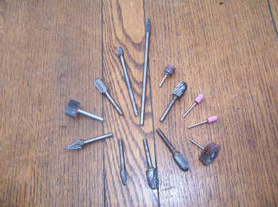
You will need a good range of rotary files if you want to do your own ports
Porting requires a good range of rotary files (with long shanks), and a drill. A small drill like a Dremel is also needed to finish off the ports with small rotary stones and rotary sanders. and it takes a long time to do the job properly (Give yourself around 1 hour per port). You don't need to do anything radical to significantly increase the are flow. If you look at the joint (or size of the gasket holes) between the heads and the manifold you will see a considerable mismatch, so the first thing to do is match up the manifold with the inlet (as in valley) gasket using a rotary file. The standard port size is 25mm x 42mm which gives a cross sectional area of 1050mm, which is considerably less than the trumpet cross sectional area of 1134mm. Opening the port up to 26.5mm x 43mm to match the inlet gasket will remove this restriction, but you do ideally need to open the manifold tracts up all the way back to the trumpet base to maintain the cross sectional area.
Good Basic Porting Practices for a Road Engine
Don’t remove material from the bottom of the port. The inlet port has a hump to help reduce the differing port flow velocities top and bottom and to help flow the gas past the valve. The cross sectional area of the port varies, and there is a “tight” spot near the push rod holes. This can be opened up to match the inlet section of the port. The port get bigger as it gets near the back of the valve, so its most restrictive point is the valve seat itself. There are significant gains to be had by re-cutting the valve seat, thought its not an option I have gone for. Porting a head by hand is an arduous task and there are no substitute for taking you time to get it right. Proceed with care and don't use tools that might scratch the valve seats as you work around the guides.
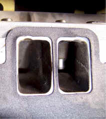
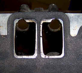
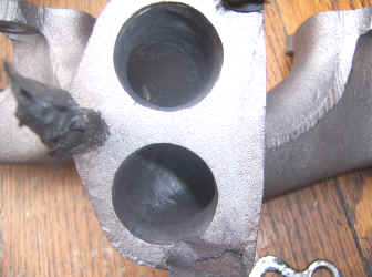
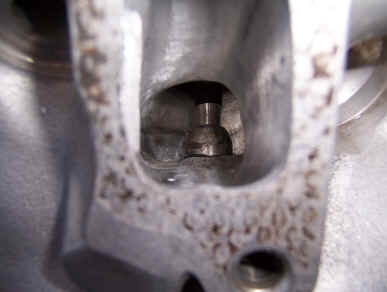
Here's some photos of just how bad the Rover castings are. The inlet trumpets are 38mm diameter, giving you a surface area of 1133 mm. The standard manifold inlet port reduces this to 37mm x 23mm = 851mm square or a 25% reduction in available port flow. By matching the ports back to the size of the gaskets you can get 1118mmsq which goes someway to restoring the difference, although ultimately valve size and opening are the most restrictive factors.
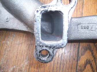
Inlet manifold opened up to match the gasket
Open the exhaust port and inlet manifold up to match the gaskets
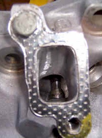
Inlet port opened up to match the gaskets. The port walls are left rough to help prevent fuel drop out and keep the fuel in suspension.
You can buy off-the-shelf bulleted valve guides. I have done the same thing with a rotary stone and a mini drill. Probably more effort than it was worth!
Changing the Camshaft - Camshaft Choice
The cam is the heart of the engine, and by keeping the valves open for longer or increasing the amount of lift of the valve, more mixture is allowed into the engine, increasing its volumetric efficiency. If the top of the cylinder was open to the open air, it would fill to 100% from atmospheric pressure as the piston descends but in real terms ports, valve guides and valves get in the way so the volumetric efficiency may drop to say 80%. Anything that can help get the air and fuel in will help improve this; BUT there is a down side, as the fuel air mix acts like a fluid, with inertia and momentum, so any given port size or valve size reaches maximum efficiency within a particular RPM range. The basic idea of tuning is to get more fuel and air in, and also get more firing strokes per minute when the engines efficiency is high. Performance cams hold the valves open for longer, (duration) and increase the lift and this raise's the rpm point when maximum power occurs. The choice of cam also depends on how much work you want to do apart from changing the actual cam. Something like the Typhoon cam needs the valve springs changing to stop them becoming coil bound on full lift and there is also a risk that there is insufficient clearance between the spring cap and valve guide, which means heads off, and shorter valve guides fitted that pushes the cost up. You can get cam followers called Rhoads lifters that don’t fully pump up until around 3500 rpm, which allows you to run a higher lift / longer duration cam and maintain lower rpm tractability. The problem is Rhoads can be very noisy before they fully pump up, and realistically the standard new Land Rover lifters are good for 6500 rpm, which is quite enough for a 40 year old design push rod engine. Max valve lift with standard springs is .464". Note the rocker ratio is 1.5:1 so the physical cam lift is correspond less. Unfortunately valve size is what lets the Rover engine down big time, even with 500 TVR heads the valves are just no where near big enough to flow the air that is required, so we are left with trying to make some decent bhp and drivability with a choice of cam.
CHOOSING CAM PARAMETERS (With thanks for the help from Rob Robinson V8 Racing)
LIFT
Basically as much lift as you can get, the better your engine will perform through the whole rev range regardless of cc's. the Rover head flows it most c.f.m when the valve is something like 700 thou from is seat, (17.7 mm) the reality here is no Rover cam lifts that far because it just can’t, 600 thou (15.2mm) is about its maximum. Lift is related to duration, you can’t have lots of lift with little duration as the valve will be being opened so fast that the cam follower will just dig into the side of the cam lobe and break, so with a 600 thou lift you are going to need 320 deg of duration, and what you now have is a full circuit race cam that will only make power from 5000 rpm upwards!
DURATION
Duration is the time the valve is lifted of its seat, too little you will have no power, and too much the car will drive like a pig. However duration, lca "lobe centre angle”, and overlap are all related, it’s not so much the duration that kills drivability its the overlap, just 10 deg can make or break the engine. The “lca” is the angle between full lift on the inlet and full lift on the exhaust lobe, by making this wider you can tame the cam for the same given duration, however what will happen is the cam with the wider “lca” will idle better, drive more smoothly, make more bhp with a wider torque curve. The cam with the smaller “lca” will only have a benefit in the mid range, around peak torque. so in my honest opinion for a road cam I like to go for around 285-290 deg of duration with a wide “lca” around 114’. This to make a good road sports cam, you can drive it down the shops with no hunting and use it on a track day as well, the same cam on a 108’ “lca” will make it more peaky in the mid range, but you will have to keep changing gears in slow traffic and it will drop off the cam quicker too, peak power will be around the same but where the 114 will still be making good power at say 6500 rpm, the 108 will be dead and buried and need a gear change. A race car is totally different I would spec a cam to work in the rev range I wanted and make the most of that rev range.
NOTE Max valve lift with standard springs is .464". Note the rocker ratio is 1.5:1 so the physical cam lift is correspond less.
Some popular cam performance and (some) specifications:
| Standard RV8 | 285" .39" 5000-5400 rpm |
| Hurricane | 262' .433" 1000-6000rpm Better than standard RV8, but a bit "soft". Good for auto boxes. |
| Typhoon | 276 '.48" 1200-6200 rpm Needs valve springs and possibly guides-. Good all rounder. |
| MC1 | Good idle, excellent drive ability, reasonable bhp. |
| MC2 | Mediocre idle, mediocre drive ability, good mid range, good bhp. |
| H404 | Very poor idle, very poor drive ability, good mid range, excellent bhp. |
| Stealth | Very good idle, excellent drive ability, moderate mid range, good bhp. |
| Piper 270 | 272' .42" 1500-6000 rpm Good idle, good mid range, poor BHP. |
| Piper 285 | 276' .440" 2000-6500 rpm. Bad idle, poor drive ability, very good mid range, good bhp but falls off the cam very quickly. |
| Piper 300 | Bad idle, poor drive, moderate mid range, good bhp. |
| Kent 200 | Very good idle, good drive, poor every where else. |
| Kent 218 | Good idle, good drive, good mid range, poor bhp. |
| Kent 214 | Ok idle, ok drive ok mid, range ok bhp. |
| Kent 224 | Poor idle, poor drive, good mid range, good bhp. |
| Kent 234 | Bad idle, bad drive, good mid range, excellent bhp. |
These are all based on the fact that you will be running standard management systems and a plenum, there are of course many more cams out there but these are the general ones you will buy.
So, to sum things up a bit, if you want a good low down nice driving torque cam, go for a cam with a max of around 270 deg duration and a lca of around 112 deg. If you aren’t bothered with idle qualities and want a good mid range cam, go for one with a low lca and around 280 deg of duration. If you want a track day cam or fast road cam go for around 300 deg and around 110 lca. If you want a good all rounder go for around 285 deg and wide 114 lca. Both Kent and Piper will make cams to what you want within reason so give them a call, the piper 285 for instance, loses nearly 25 bhp over the 404 at the top end, this on a controlled dyno not a rolling road, but it gains around 10 ftlb at around 200-3000 rpm, but if you asked piper to grind it on an lca of say 110’ you would only be losing around 10 bhp at peak, but gaining around 20 ftlb at 2000-3000. Please note however cams cannot be judged against other cams on rolling roads, especially different rolling roads, there are too many variants, all the way from the air filter to the oil in your gearbox and diff!
Throttle bodies against plenums and cams
What I briefly said earlier with large overlap cams, this will murder an engine running a plenum, where as on throttle bodies it tends to smooth things out a bit. Take a single plenum and all 8 cylinders draw from this one opening, which is good as each cylinder can draw as much air as it wants with no restrictions as far as air flow is concerned. The BIG DOWNSIDE TO A PLENUM, on the overlap period part of the cam, this is where both exhaust and inlet valve are open at the same time, i.e. at the end of the exhaust stroke where the piston is forcing the burnt gas out the exhaust port the inlet valve opens before the exhaust is shut, instead of the unwanted rubbish going out the exhaust it is sent back up past the inlet valve and into the plenum. This is more aggravated by the fact that the next cylinder is sucking hard and will suck the waste out of the disposing cylinder into the good one, so instead of the new cylinder getting a good charge of fresh air and fuel it has 20 or 30% of nothing that cant be ignited, hence poor combustion poor idle and low power. This is only a problem at low rpm as at high rpm you have the advantage that the exhaust manifolds "should" be scavenging the fresh inlet charge into the cylinder. If you have the money to go to throttle bodies then this is where the biggest gain is going to come in the low to mid range, on the overlap period each cylinder can only contaminate its own cylinder, and part of this will be lost to the atmosphere anyway, so generally lets say at below 3000 rpm a plenum is giving a cylinder 70% of fresh charge to be ignited a set of throttle bodies will be giving 90% at the equivalent rpm all this = more ft-lb of torque, just be careful you don’t go too small on the throttle bodies or this will hurt the top end breathing, you have gone from a 72 mm plenum and as I said each cylinder will see 72 mm down to what ever size your throttle bodies is.
Rob Robinson
Changing the cam basically involves the following procedures. This is NO substitute for reading the Haynes manual!
- Drain the cooling system, including the blocks
- Remove the Bonnet, radiator and steering rack mounting bar. The rack can be left dangling
- Remove the inlet and Plenum chamber
- Remove the trumpet base and inlet manifold and injectors
- Remove the V gasket
- Remove the rocker covers
- Remove the rocker shafts
- Remove the push rods. Number them as you go so the go back into the same positions
- Remove the cam followers. Note: Don't re-use the old ones, they will knacker a new cam!!
- Remove the oil filter. (To prevent oil spillage)
- Lock the engine by putting the car into 5th
- Remove the crank pulley and timing cover
- Remove the camshaft end bolt
- Remove the crank sprocket, cam sprocket and spacers
- The cam will simply pull out. Be very careful as you go to prevent the cam lobes scratching the cam bearings
- The replacement cam should slide straight in with lots of cam lube
Fit new cam followers, but firstly force as much oil into them as you can through the tiny hole in the side. An oil can with a bit of heat shrink tubing over the end makes a good "nipple". Oil will emerge around the piston in the follower when its full. If you omit this process it takes longer for the follower to fill up and open the valves, so the engine will not start straight away, which is very bad news for a new camshaft as the loads on the cam tip are very high at cranking speed, so the cam tip gets damaged instead of bedding in.
Setting up cam timing on the Rover V8
If you are changing the camshaft for a different type it is necessary to “dial in “ the camshaft to ensure the best possible performance from the cam.
Before doing this you will need to collect the following:
- 1 x 360 degree plastic protractor (W.H smiths or the like)
- 2 x Bicycle spokes or very stiff wire
- 2 x dial test indicators (DTI) (Ebay around £10)
- ½ “ x 1/8” Flat metal bar. (B&Q) This is needed to make some simple brackets to hold the dial test indicators. Dimensions are far from critical as long as it wont bend under slight load.
Your dial test indicators are needed to make 2 measurements.
1) No 1 piston top dead centre
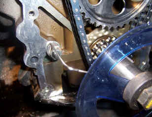
Using the metal bar make up a bracket that will hold the dial test indicator on the head with its shaft pointing down into the plug hole in a readable position. The exhaust manifold mounting points will do to mount the bracket. Remove the tip of the DTI, and use a bicycle spoke to extend the shaft down to touch the top of the piston as it nears top dead centre. I would recommend you bend the spoke tip in a loop so not to scratch the piston top. Cut the spoke so the DTI is near mid point at top dead centre, so not to force the DTI. Hold the spoke with tape or heat shrink tubing so it does not drop into the engine!!
Simple metal bracket holding the DTI in number one plug hole, with a bicycle spoke extending the DTI shaft down to the top of the piston. A bit of yellow heat shrink tubing stops the spoke dropping into the engine. There is a screw tread in the end of the DTI if you can find the correctly threaded shaft!
You also need to be able to exactly measure the crankshaft degrees from top dead centre and as you have no timing cover you have no reference. The DTI in number 1 plug hole is used to find exact top dead center and zero the protractor.
2) No 1 inlet cam follower height
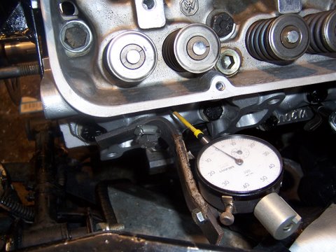
Make another bracket to hold the DTI on the head with the shaft pointing down the push rod tube for No 1 inlet valve. Use a rocker mounting points for a fixing point for the bracket. Cut a bicycle spoke to reach from the DTI tip to the top of the cam follower or number 1 inlet, and again the follower at full lift needs to be somewhere near mid point on the DTI.
Here the DTI is mounted to a simple bracket and spacer, off one of the rocker pillar fixing points. The DTI shaft is extended down with a bicycle spoke to touch the center of number one inlet valve follower to measure the point of maximum lift.
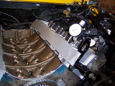
Using the crankshaft pulley washer, scribe a circle around the inside of the washer on the central axis of the protractor. Then cut out a hole to allow it to be bolted to the end of the crank. (A small drill like a Dremmel and rotary file is the best bet to cut the hole).
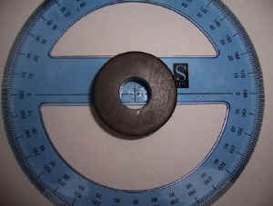
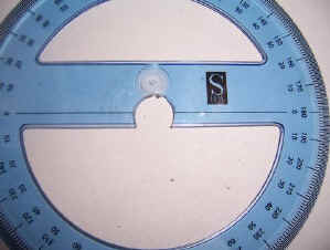
Fit the protractor to the end of the crank. Make up a metal pointer to bolt to a timing cover stud and line it up with the edge of the protractor. (its worth putting a point on the metal pointer for accuracy).
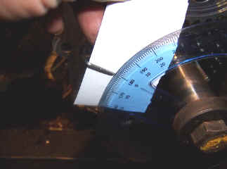
Rotate the engine until number one is top dead centre and fiddle about with the pointer/ camshaft bolt so it aligns with one of the 0’ marks on the protractor and nip up the crank pulley bolt..
NOTE: Any timing set worth its salt will have some sort of adjustment system. If you are using the standard cam sprocket sets, (NOT recommended) there is no adjustment available.
Method 1 timing:
Set the basic timing by aligning the marks to 0 degrees on the adjustable sprocket set according to the manufactures instructions supplied with the sprocket chain set.
Rotate the engine clockwise until the inlet follower lifts and note the degree value for maximum lift of the inlet valve for the specified cam. (A typical value would be 110’.) The protractor may only go up to 90’ so add the extra as it counts back down.
Compare the value on the value read on the protractor at maximum inlet valve follower lift with the cam spec’. Alter the cam timing to suit according to manufactures instructions supplied with the adjustable sprocket chain set.
Repeat until its within about 2’, which realistically is about as close as you can get.
Method 2 or if you get completely lost in the engine cycle (easy to do!)...
Rotate the engine crank until the point for maximum lift for No 1 inlet for the particular cam.
Rotate the camshaft until number one inlet valve follower is at its maximum lift.
You can now see the positions of the keyways on the crank and camshaft, and assuming you have some sort of variable cam timing set try and align the chain, and sprockets to fit. Once fitted rotate the engine through 2 revolutions and recheck the values. If you have this near correct the manufactures alignment marks should be near alignment.
Things to remember if you get confused:
The inlet valve will start to open before top dead center, so make a mental note of where you are in the engine cycle. The exhaust should just also be closing. If its not, you are on the compression part of the cycle, so rotate the crank another 360’ This is a fiddly job at best, and may require a lot of adjustments until it’s within spec’.
Engine Reassembly Notes
Again read the Haynes manual on reassembly, but there are a couple of points worth adding:
1) Head gasket. On the 3.9 this is a thin tin gasket, that tend to leak as they get older. On the later engines a composite gasket is used that seals much better, but is considerably thicker, and reduces the compression ratio, which goes against the requirement for more power. It's possible to skim the heads about .03" to compensate, but not forgetting on a V engine dropping the heads changes the gap for the inlet manifold to sit into, so only very light machining can be done. One reason for the tin gasket failing is an uneven load on the head cause by a row of extra bolts above the exhaust ports, that has been removed on later heads. On the 3.9 heads best bet is to only tighten these bolts to around 25 ft/lb (or half the origional torque settings) so they fill the holes but don't warp the head. I have used a tin gasket, with additional red Hermetite gasket sealant as an additional precaution. There is more information on the RPI web site.
2) Cam follower Preload. This does not even get a mention in the Haynes manual, but basically the hydraulic followers need to be "preloaded" within a tolerance band to function properly. As there is no push rod adjustment, the only way to alter the preload is to adjust the rocker pedestal heights with metal shims. A preload shim kit is around £20 and comprises of 2 sets of 8 shims, that can be used to raise the pedestal, and as the tolerances are quite wide (.032 to .06") normally one of the two sets will do. In my case the standard cam had no shims, but with a Piper cam and new followers I had to lift the pedestals by .017". Again this process is covered in great depth on the RPI web site.
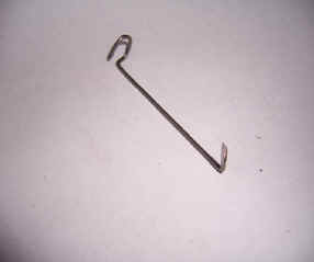
3) Before you start, it is most important to have the engine oil system pressurised and everything primed and ready to go. To raise the oil pressure, leave the distributor out to expose the oil pump drive, and using a variable speed electric drill with a tube with one end flattened to rotate the oil pump clockwise until oil is seem seeping around the rocker shafts and the oil pressure gauge has started to rise. On refitting the distributor make sure the rotor arm and distributor/oil pump drive all lock together with the rotor arm positioned towards number one plug lead with number one cylinder on top dead center on the compression stroke. Make sure all the plug leads are in the correct position and spaced correctly to avoid cross firing. Make sure you have no air leaks around the plenum chamber, and the cooling system is full. With the battery fully charged, turn on/off the ignition system several times to pulse the fuel pump to pressurise the fuel rail and remove any air locks. Finally remove one of the blanking plugs from the Plenum chamber and give a good squirt of easy start into the chamber, and replace the plug. Hopefully the engine will then fire and run on initial cranking. If it does not, stop and investigate why not, don't keep cranking. It does take time for the hydraulic followers to fully pump up, but the easy start should help overcome the initial lack of cylinder charge. Assuming the engine has started, lift the RPM to around 2500 rpm and hold it there for around 20 minutes to bed in the new cam shaft. Alternatively take the car for a run, but don't let the car tick over for any period, as the cam tip loads are very high at low speed, and can damage the lobe tip before it beds in fully.
See also section on chipping