IGNITION SYSTEM
The Electronic Ignition system used on the Rover V8 is a basic system using mostly parts from much older generation of cars, with the exception of the electronic switching system used to drive the coil. It only uses a single coil that has to provide a reliable spark up to say 6200 rpm, so its worth taking a look at how this trigger system works, in combination with the coil and HT leads.
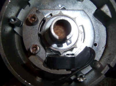
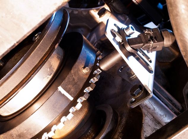
How the trigger works inside the distributor
The trigger rotor has 8 lobes on it, corresponding to the 8 cylinder firing cycle. The trigger system is a simple magnetic system and the curved metal block on the left is a strong permanent magnet. This transfers some magnetic field into the 8 lobe rotor at one end of the magnet, whilst the other end of the magnet follows around to the back of the trigger head, that comprises of a metal core and simple wire winding. When one of the trigger lobes aligns with the metal core of the trigger head through a small air gap it completes a magnetic loop through the core of the trigger, and induces a small electrical voltage into the trigger coil that surround the core. (The black plastic body seen here). This is then fed to the outside of the distributor with two high flexible wires. These have to be flexible to account for the movement of the timing plate when a vacuum advance is applied.
The trigger head provides a small AC signal that is then fed into an "ignition amplifier" used to boost the trigger voltage to a point it can be used to switch the coil. The rotor is carefully designed to provide to provide enough dwell period to allow the coil to charge to the point a good spark can be maintained even at high RPM. As the trigger provides a semi sinusoidal type output of a variable voltage depending on the rotor RPM, the design of the ignition amplifier is important to ensure the switching on and switching off point of the coil is maximised for the best maintenance of both spark voltage and duration. As the available dwell period (coil switched on time) becomes very short on a V8 engine at high RPM, some compromises have to be made in both the dwell period, and spark duration, resulting in both reduced peak HT voltages and reduced spark burn time, dropping off quite sharply above 5000 rpm. There is however enough "headroom" in the Lucas design to allow for this and still maintain a good spark.
Simple Ignition Amp & Trigger Head Test
Loss of trigger signal to the coil will normally cause the rev' counter to drop rapidly to zero, even if the engine is turning, but a simple test can be done on a static engine to check the basic operation.
Remove the top of the distributor, and plastic cover covering the trigger mechanism. Remove the king HT lead from the centre of the distributor cap, and tape it up so the end connector now forms a good spark gap to chassis. Up to 1 cm should not be an issue for the spark to jump. Be sensible about this bit to ensure you don't electrocute yourself, so keep the lead tip well away from your body!!
Rotate the engine slowly until one of the rotor tips aligns with the magnetic pickup, and then turn on the ignition. The fuel injection system should pulse the fuel pump as per normal during start up for a couple of seconds. Now take a small flat screwdriver and rapidly tap and remove it down to fill the air gap between the rotor and the trigger head. This should be enough to complete the magnetic circuit as if the engine where running, and a crack should be heard from the coil / king lead as a spark is created. The ECU should also pick up this trigger pulse and fire the fuel pump for its 2 second period again. If this fails try putting a magnet on the side of the screwdriver and repeat the test. If this fails you could have a faulty trigger head (the wiring goes open circuit sometimes), amplifier, amplifier connections, HT coil or loss of supply to the coil.
HT Leads
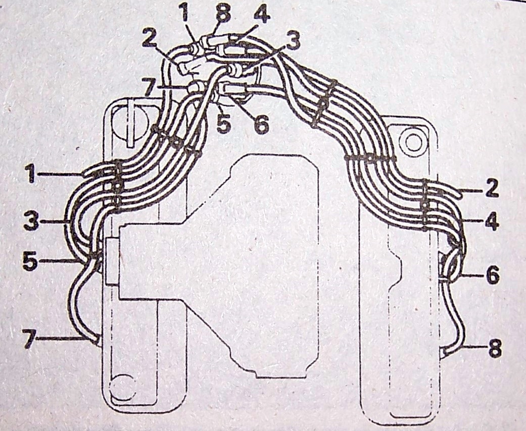
The routing of the HT leads is critical to get the best from the distributor system used. If the leads are grouped closely together then cross firing can occur between the leads where HT voltages are induced between the leads and can lead to a plug firing at the wrong time, and subsequent misfires. Below is the correct cable routing:
"Improvements" to the Ignition System
Ignition Amps
You will find some outrageous claims for aftermarket ignition amps that will produce fantastic secondary voltages, but this is a complete fallacy. The peak HT available is purely dependent on the type of HT coil, and its allowed dwell period. In ideal conditions the stock coil will produce about 35kv open circuit, but this will drop to around 25kv as the RPM drops. This peak voltage is irrelevant anyway, as the coil voltage will only rise as far as is needed to start the spark- typically 5-20kv. Once the spark has started the next bit is to keep the spark burning for as long as the engine needs it to get a good flame front to ignite all the available mixture, and then return the coil to its dwell period, ready for the next spark. Its possible to juggle the peak HT voltage against the spark duration by altering the trigger point the amplifier switches the coil on and off, but how much effect this has in the real world if difficult to ascertain. The standard ignition amps works very well on petrol (other fuels may need different spark characteristics), and will not be improved upon by switching to a "high power" unit.
HT Leads
There is a great tendency to assume that resistance in the HT leads is a bad thing, and leads to a weak spark. This is true if excessive resistance is used, but some resistance is needed to control the rate at which the coil discharges into the spark. If you say used plain copper leads the rate of discharge of the coil is purely dependent on the internal resistance of the coil secondary. This leads to a vary rapid collapse of the magnetic field in the coil, so you get large voltage spikes in the coil primary as it switches, and large amounts of radio interference generated by the plug leads themselves. Both of these factors are bad news for any surrounding electronics that can get spiked. It also produces large primary spikes the ignition amplifier and rev counter have to deal with. Typically the back EMF (spike voltage) the amp' has to deal with would be 2-300 volts with resistive leads, but can go as 600 volts if copper leads where used. Although the spark will be very hot, its duration will be short due to the rapid discharge of the coil, which may not be ideal if the combustion chamber does not support a reliable flame front, where a longer spark duration would allow all the mixture to ignite. Using copper leads is obviously a very bad idea, but there are low resistance HT leads sold to the un wary as a "performance upgrade" at great expense. These have a coiled conductor running down the core of the HT lead that produces a magnetic field as the coil discharges, that produces its own voltage that counteracts the coil discharge, in a process known as reactance. This does limit the discharge current of the coil to an extent, and limit the radio interference and back EMF issues, but less so that standard resistive leads. Its a common mistake to simply measure the DC resistance of HT leads in K ohms per foot of lead and compare them, but this does not take the magnetive reactance of the lead when presented with a high frequency high voltage spike, although the issue here is the standard system is set up to work well with resistive leads and low resistance leads will not improve the combustion process at all. If you find people saying low resistance leads have transformed their car, its usually due to the fact that the original HT leads had reached the end of there useful life anyway. You will find NO documented evidence to support the use of low resistance leads as a way of gaining any BHP over decent quality OEM leads, only the much lighter wallet will make the car any faster.
In terms of how much resistance is good or bad, you need at least one resistive element between the coil and spark plug tip, be it normal HT leads, suppressive plug extenders or resistive plugs. If you fit low resistance leads you are likely to need to add resistive plugs to compensate for the loss of resistance in the system.
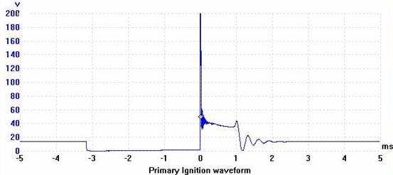
This diagram shows a typical voltage across the ignition amplifier during one cylinder ignition cycle, showing the 200 volt spike that is controlled by using resistive HT leads.
Ignition Replacement Upgrades
123 Ignition
This is a well made replacement distributor system with an electronic trigger system and a fully map able solid state advance curve via a USB interface. Getting rid of the vacuum advance system and bob weight ignition advance obviously is no bad thing, but it still retains the issues of lack of dwell at high RPM on a single coil. It is good if you wish to retain the look of your engine, and want something that plugs in easily as an upgrade, but is quite expensive for a limited upgrade.
Electronic Distributorless Ignition System (EDIS) for a Ginetta G33 By Miel Van Hutten
The Basis
The G33 engine configuration is a 4.0 litre V8 engine, manufactured in 1992 by TVR Power. The fuel system is managed by a Lucas 14 CUX electronic fuel injection computer (Lucas Hotwire), which receives inputs from various sensors as commonly used in the Range Rover Classic. The ignition is a single Bosch coil and a Lucas 35DLM8 distributor with an amplifier and vacuum unit. With this configuration the engine delivered a power of 244 hp @ 5.318,6 rpm and 353 Nm torque @ 4.172,9 rpm.
Why install an EDIS?
The following reasons were reasons to replace the present ignition with a ‘wasted spark’ EDIS:
- Improved fuel consumption
- Better throttle response and drivability
- Reliable and maintenance free ignition system
- Adjustable ignition maps by means of a laptop based application
Since the fuel side of the engine management functions reasonably well with the Lucas EFI, it was decided not to invest in a integral engine management system, combining fuel and spark, such as i.e. Megasquirt or Emerald. For such a system it is necessary to replace the cabling, which is a time consuming job and probably not worth the added value of an integral engine management system. The mechanical modifications necessary for a ‘wasted spark’ EDIS, can, however, be used for a future integrated engine management system, should you require so in the future.
What do you need?
A programmable EDIS has been used on many American engines during 1985 – 2000, especially on Ford engines. The eight cylinder engines made use of so called Ford EDIS8 modules. Also in the USA an open source DIY programmable ignition system was introduced by Brent Picasso (Autosport Labs) Loose components such as circuit boards and components could be purchased, which you had to solder and assemble yourselves. Due to continuing miniaturization the ‘do-it-yourselves’ was abandoned and the system is now delivered ready assembled.
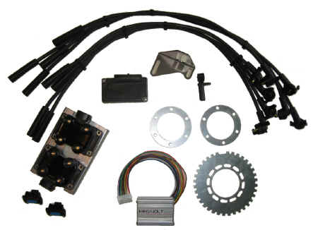
For a V8-engine you would need the following:
- A cog wheel for the crankshaft, for a V8 a so called ’36-1 Trigger Wheel’
- VR crank sensor
- Ford EDIS8 module (these are not produced anymore, but are available second hand from breakers)
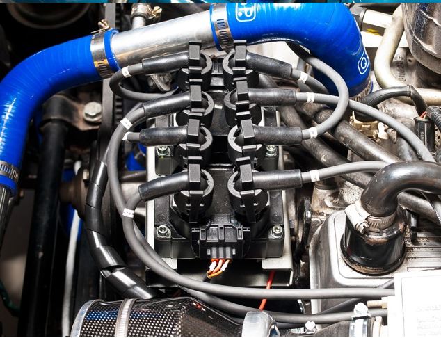
- Two coil packs (Ford first generation)
- A set of ignition leads with boots that fit the coil packs
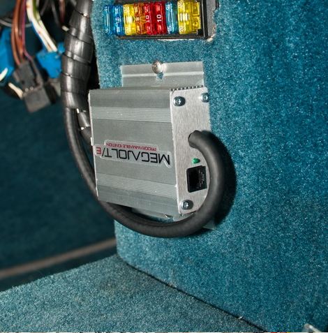
- Ignition management module, such as Megajolt/E
- Tacho driver
- USB cable to connect the ignition management system to a laptop computer (only Windows based!)
- Support brackets for the VR-sensor and coil packs
- A ‘Dinky Dizzy’ as a dummy to drive the oil pump of a pre-serpentine V8 engine
- Suppliers of these materials are Trigger-Wheels.com and MEGASQUIRTV8 Ltd. (The latter for an better VR sensor and the ‘Dinky Dizzy)
Mechanical Installation
Dismantling of the bonnet, cooling radiator and steering rack in order to gain access to the crank pulley. Beware: By lifting the steering rack to gain access, I bent the steering column, which later on resulted in problems with local MOT. Better to also take the steering column out too!
Removal of the crank pulley
Positioning and fix the ‘Trigger Wheel’ to the crank pulley
Positioning and fix the bracket for the VR-sensor
Positioning and fix the bracket for the coil packs, such that the electrical connections between VR sensor, EDIS8 are as short as possible.
Removal of the ignition coil
Removal of the distributor (note the position of the rotor, in case you might have to replace the distributor).
Install the ‘Dinky Dizzy’ in the hole of the distributor to ensure operation of the oil pump.
Refit steering system, radiator and hood
Mechanical
Special care is necessary to install the ‘Trigger Wheel’ correctly to the crank pulley. The missing tooth must be positioned 5 teeth before TDC (Top Dead Center) for a V8 engine.
Removal of the crank pulley was difficult. Eventually an air driven socket was able to loosen the nut.
The brackets from Trigger Wheels as delivered in the package were of good quality, however it did not fit to the V8 engine.
The ideal position for the coil packs appeared to be at the location of the former distributor. The ‘Dinky Dizzy’ makes this room available. A custom made bracket had to be made, very neat, but costly!
The bracket for the VR sensor is too weak, and vibrations can cause misfires. An additional web plate would make the bracket much stiffer. The distance of the VR sensor to the ‘Trigger Wheel’ is approximately 0,5 – 1 mm so the ‘Trigger Wheel’ has to be positioned perfectly concentric to the crankshaft!
Electrical Installation
- Connect the VR sensor to the EDIS 8
- Connect EDIS8 to the coil packs
- Connect the EDIS8 to the Ignition Management module (Megajolt/E)
- Connect the EDIS8 to the 14 CUX ECU module
- Make use of shielded cables
- Connect the tacho driver to the 14CUX ECU module making use of diodes
Notes to the installation works
The electrical installation instructions and charts require careful study in advance.
After installation of all components and cabling with shielded cables, it is advisable to start the engine without connection to the ignition module. The engine should start in ‘limp home mode’, whereby the EDIS8 takes care for a fixed 10 degrees advance. At first this did not work out! The 14CUX ECU requires a signal (formerly from the coil) to activate the injectors. Now that separate coil packs are used, you cannot use a single trigger take of point from just one coil pack, so a separate diode board is need to add all the separate coil pack pulses together for both the ECU trigger and the Tacho’ signal. The cables as supplied were useless for this and needed to be made from scratch.
The ignition leads have to be carefully connected. It is important to identify the coil packs in groups of two and indicating them by means of capitals A to E. Identify the cylinder numbers and firing order and identify every lead with that number.
Positioning of the ignition module (‘Megajolt’) in the car at the position of the passenger side of the car under the dashboard. Such that a laptop can be connected during testing.
The timing advance vacuum information to the Megajolt is delivered by a rubber hose from the plenum. The original connection to the plenum appeared to be a ‘ported vacuum’, that resulted in a false information when the throttle was closed. It was easy to provide a new connection to the plenum by drilling a new hole away from the throttle plate.
Mapping of the Ignition System
So far the basis map was applied as from the Lucas 35DLM8 distributor. The map was entered via the software application as a 10 by 10 matrix.
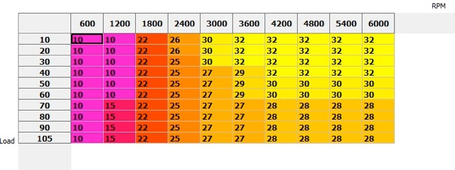
So far the improved fuel consumption has not yet been accomplished. After discussion on another forum (piston heads) it may appear that the present ignition map is very conservative and might have been derived from the existing distributor advances. A further 10 degrees advance between 2k and 3,5k rpm under light load might be possible. Another rolling road session shall be necessary to investigate this.
Credits:
Installation Work
Onixx Starcraft BV – Hans Vooys
Mapping:
Easy-Tech Automotive Engineering & Electronics – Paul Welther or Info@easy-tech.nl